Removal Procedure
Notice: Handle the oxygen sensors carefully in order to prevent damage to the component. Keep the electrical connector and the exhaust inlet end free of contaminants. Do not use cleaning solvents on the sensor. Do not drop or mishandle the sensor.
Notice: Refer to Heated Oxygen Sensor Resistance Learn Reset Notice in the Preface section.
Important: Remove the heated oxygen sensors (HO2S) with the engine temperature above 48°C (120°F). Otherwise the HO2S may be difficult to remove.
- Remove the air deflector. Refer to Front Air Deflector Replacement .
- Remove the connector position assurance (CPA) retainer.
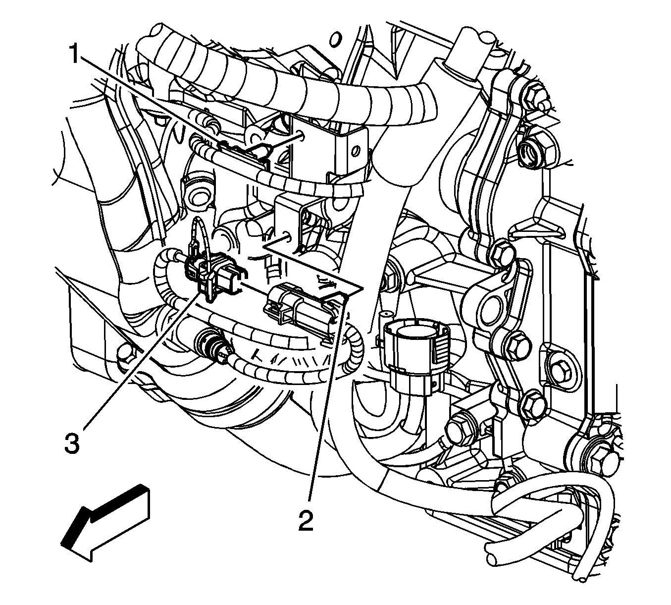
- Disconnect the engine harness electrical connector (3) from the heated oxygen sensor (HO2S).
- Remove the HO2S clip (2) from the engine bracket.
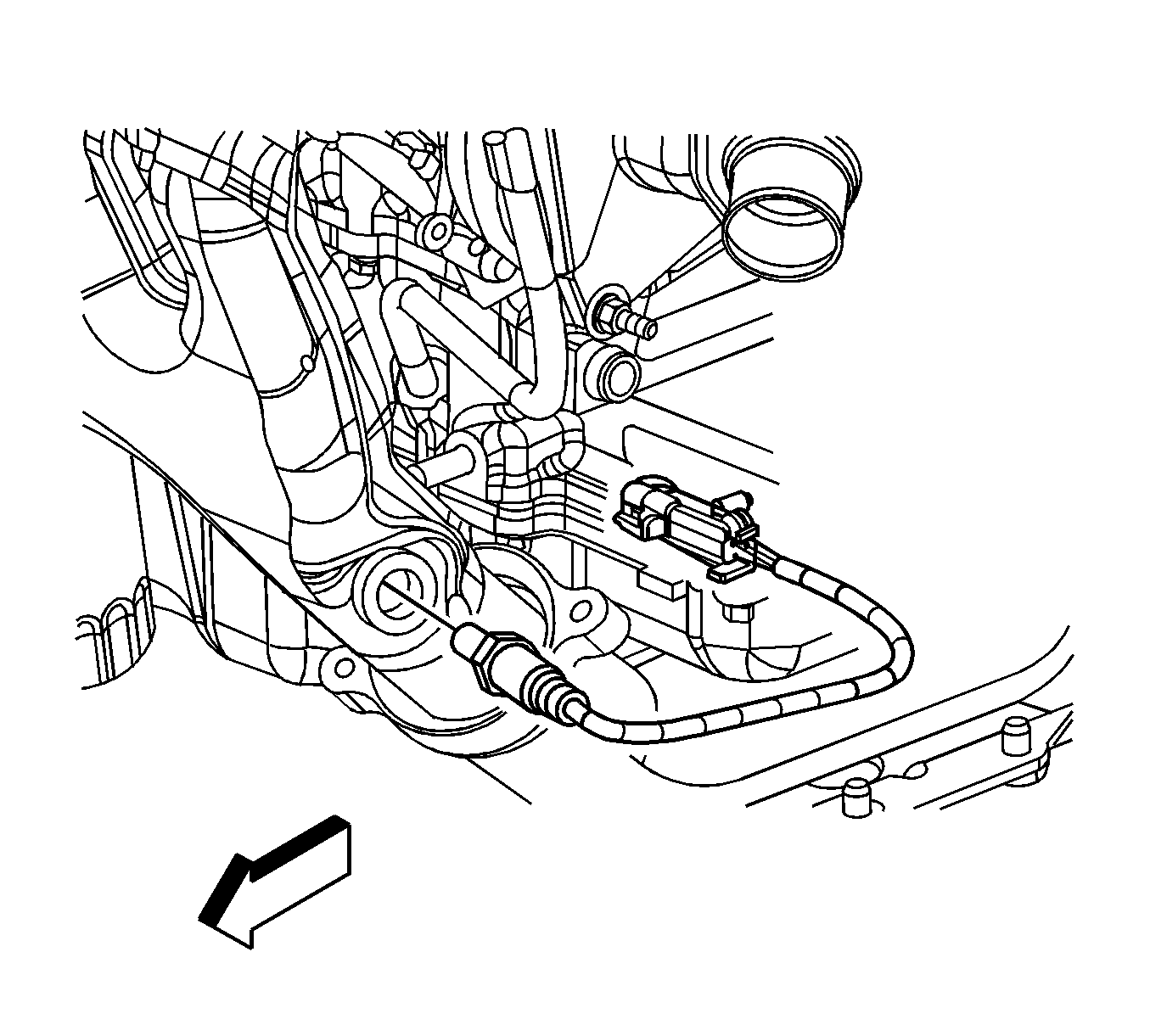
- Remove the HO2S.
Installation Procedure
Important: A special anti-seize compound is used on the HO2S threads. The compound consists of liquid graphite and glass beads. the graphite tends to burn away, but the glass beads remain, making the sensor easier to remove. New, or service replacement sensors already have the compound applied to the threads. If the sensor is removed from an exhaust components and if for any reason the sensor is to be reinstalled, the threads must have anti-seize compound applied before the reinstallation
- If reusing the old HO2S, coat the threads with anti-sieze compound, GM P/N 12377953 or equivalent.
- Install the HO2S.
- Connect the engine harness electrical connector (3) to the HO2S.
- Install the CPA retainer.
- Install the HO2S clip (2) to the engine bracket.
- Install the air deflector. Refer to Front Air Deflector Replacement .
Notice: Refer to Fastener Notice in the Preface section.
Tighten
Tighten the sensor to 41 N·m (30 lb ft).
