GM Service Manual Online
For 1990-2009 cars only
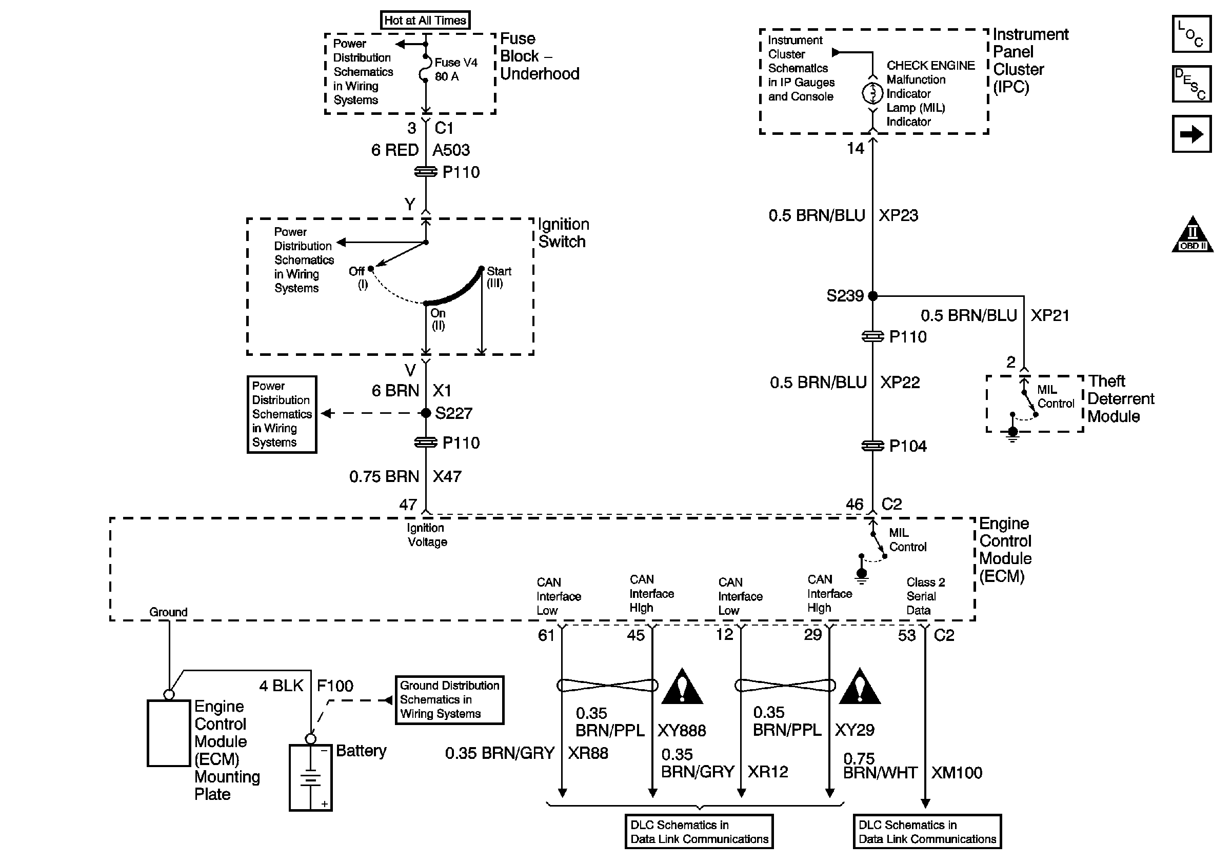
Figure 1:

Power, Ground, Serial Data, and MIL


Object Number: 788031  Size: FS
Master Electrical Component List
Electronic Ignition (EI) System Description
Engine Controls Power Relay
Engine Controls Schematic Icons
Battery Cable Bus
Power, Headlamps On Required, ABS, Traction Control, Sport Mode, Check Engine, Brake To Shift, Air Bag, Charging System Brake Pad Wear, Low Washer Fluid, Seat Belt Leveling, Brake and Cruise Indicator
Underhood Fuse Block Fuses V1 and V4, and Ignition Switch
G103 (1 of 8)
Engine Controls Schematic Icons
Serial Data and CAN Interface
DLC Pins 3 and 7
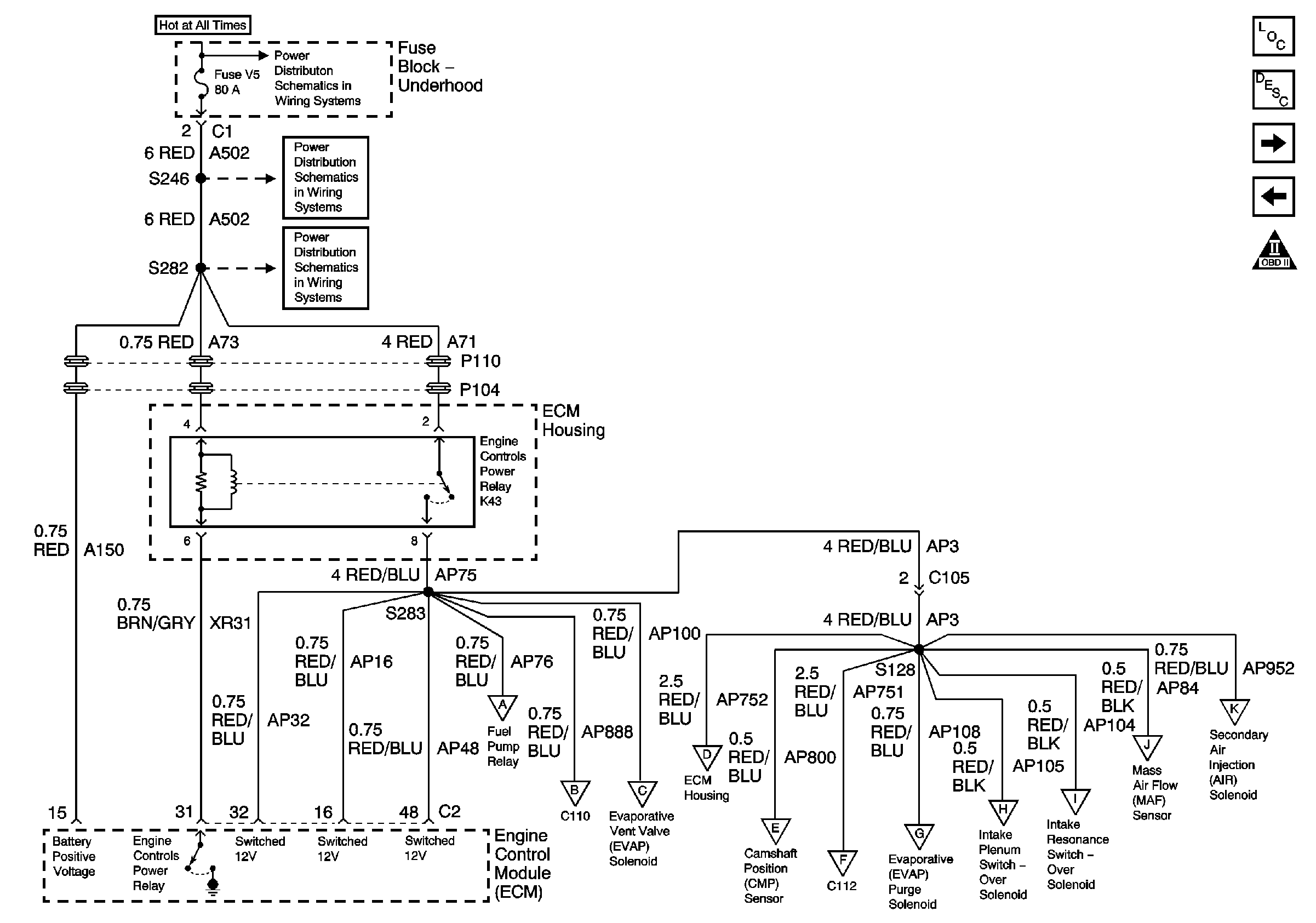
Figure 2:

Engine Controls Power Relay


Object Number: 788032  Size: FS
Master Electrical Component List
Electronic Ignition (EI) System Description
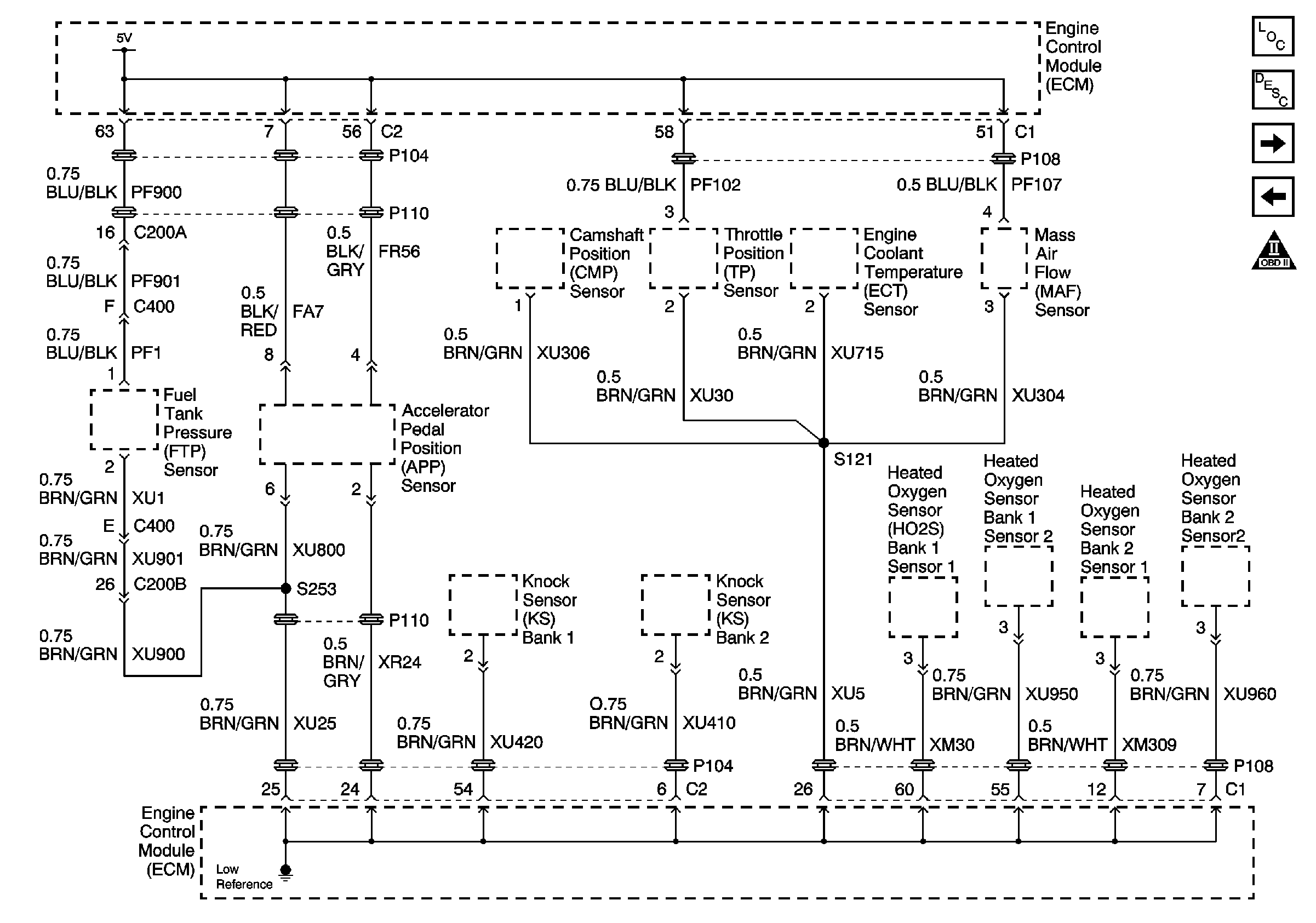
Engine Data Sensors - 5V and Low Reference
Power, Ground, Serial Data, and MIL
Engine Controls Schematic Icons
Battery Cable Bus
Underhood Fuse Block Fuse V5 and Fuse Block Fuses 6, 7, 20, and 25
Fuse Block Fuses 4, 18, and Engine Controls Power Relay
Fuel Controls - Fuel Pump
Device Controls - AIR Injection and Intake Air Controls
Fuel Controls - EVAP Controls
Engine Data Sensors - HO2S
Ignition Controls - Sensors
Fuel Controls - Fuel Injectors
Fuel Controls - EVAP Controls
Device Controls - AIR Injection and Intake Air Controls
Engine Data Sensors - Pressure and Temperature
Device Controls - AIR Injection and Intake Air Controls
Figure 3:

Engine Data Sensors - 5V and Low Reference


Object Number: 788033  Size: FS
Master Electrical Component List
Electronic Ignition (EI) System Description
Engine Data Sensors - Pressure and Temperature
Engine Controls Power Relay
Engine Controls Schematic Icons
Figure 4:

Theft Deterrent Module, Throttle Position, Engine Collant Temperature, and Mass Air Flow Sensors
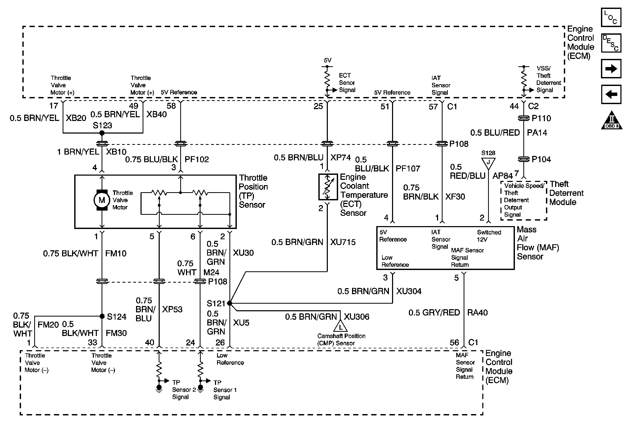

Object Number: 788034  Size: FS
Master Electrical Component List
Electronic Ignition (EI) System Description
Engine Data Sensors - HO2S
Engine Data Sensors - 5V and Low Reference
Engine Controls Schematic Icons
Engine Controls Power Relay
Ignition Controls - Sensors
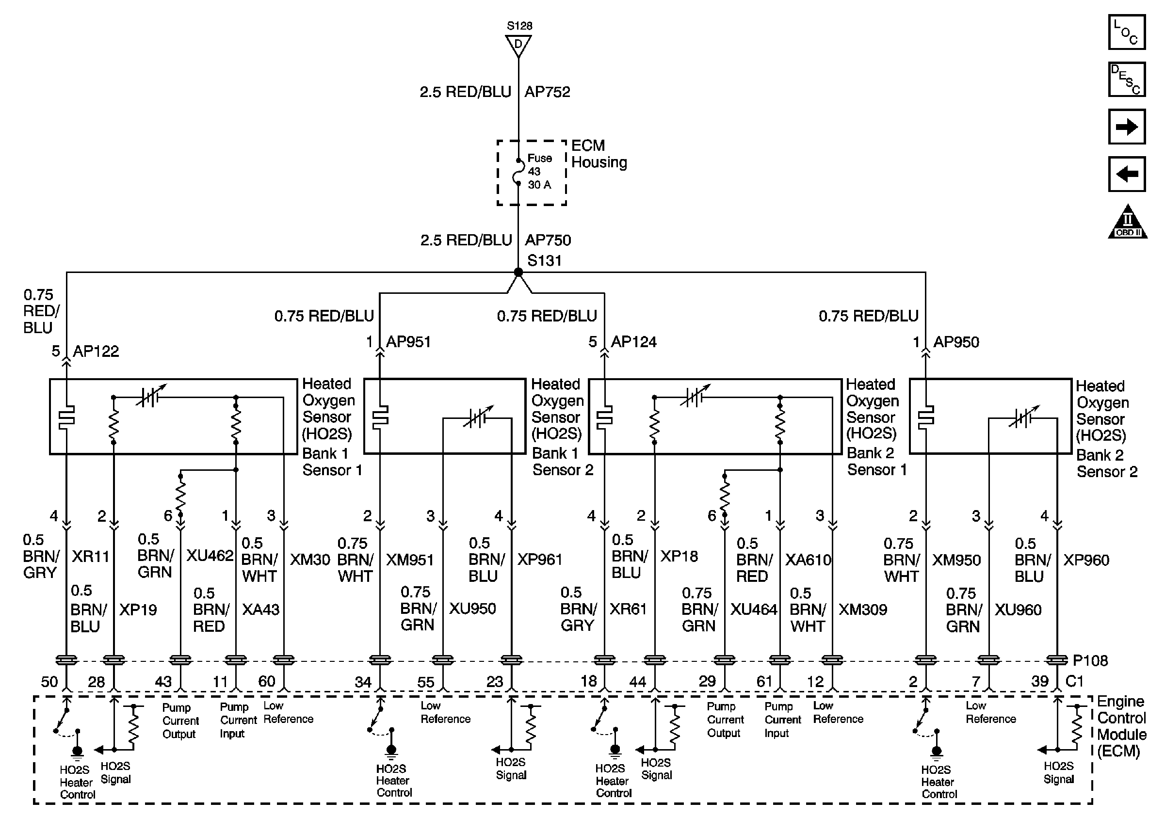
Figure 5:

Heated Oxygen Sensors (HO2S)


Object Number: 788037  Size: FS
Master Electrical Component List
Electronic Ignition (EI) System Description
Engine Data Sensors - APP Sensor
Engine Data Sensors - Pressure and Temperature
Engine Controls Schematic Icons
Engine Controls Power Relay
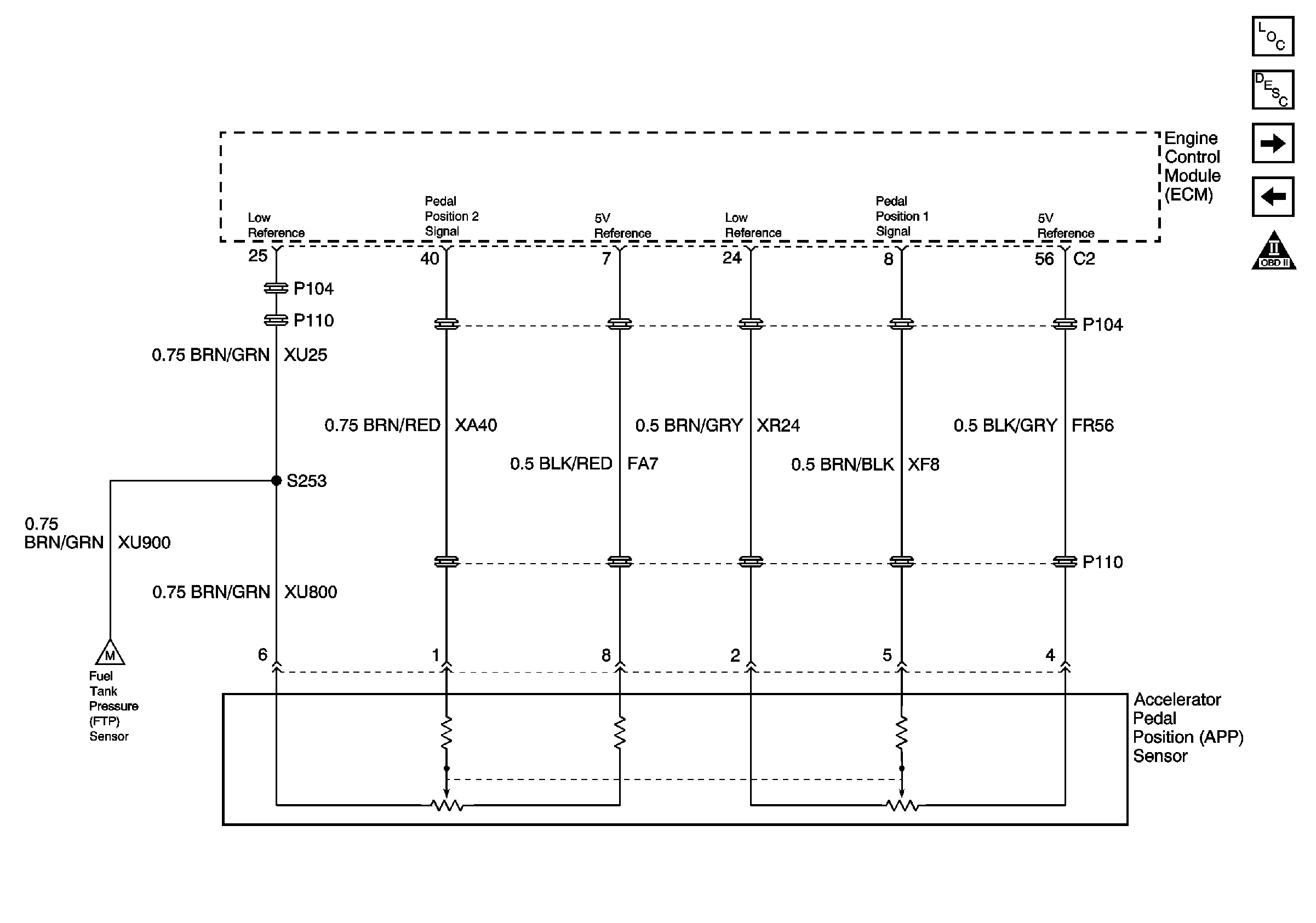
Figure 6:

Accelerator Pedal Position Sensor


Object Number: 788038  Size: FS
Master Electrical Component List
Throttle Actuator Control (TAC) System Description
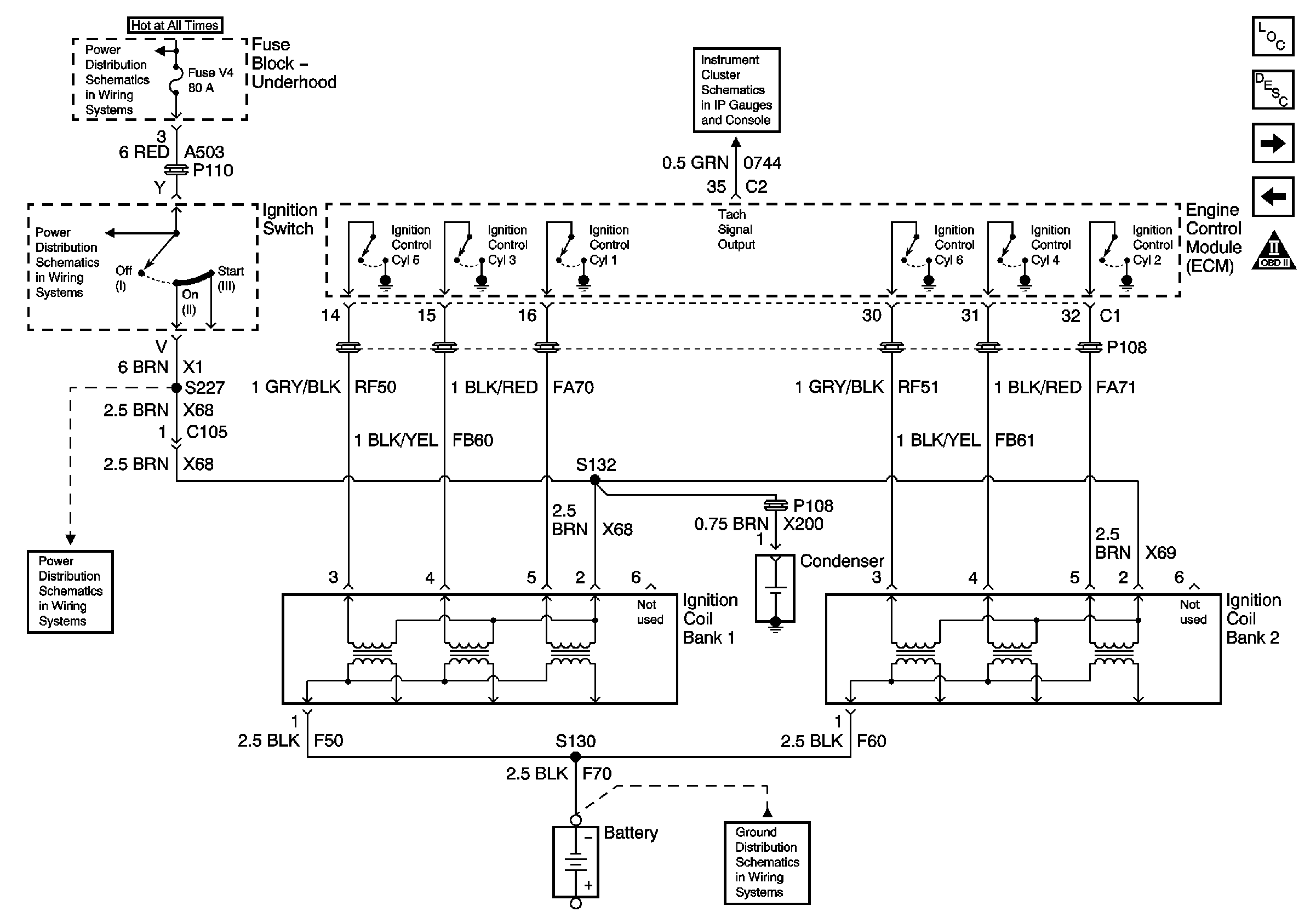
Ignition Controls - Ignition Coils
Engine Data Sensors - HO2S
Engine Controls Schematic Icons
Fuel Controls - EVAP Controls
Figure 7:

Ignition Coils


Object Number: 788040  Size: FS
Master Electrical Component List
Electronic Ignition (EI) System Description
Ignition Controls - Sensors
Engine Data Sensors - APP Sensor
Engine Controls Schematic Icons
Battery Cable Bus
Tachometer, Speedometer and Overspeed Indicator
Underhood Fuse Block Fuses V1 and V4, and Ignition Switch
G103 (1 of 8)
Figure 8:

Camshaft Position, Crankshaft Position, and Knock Sensors
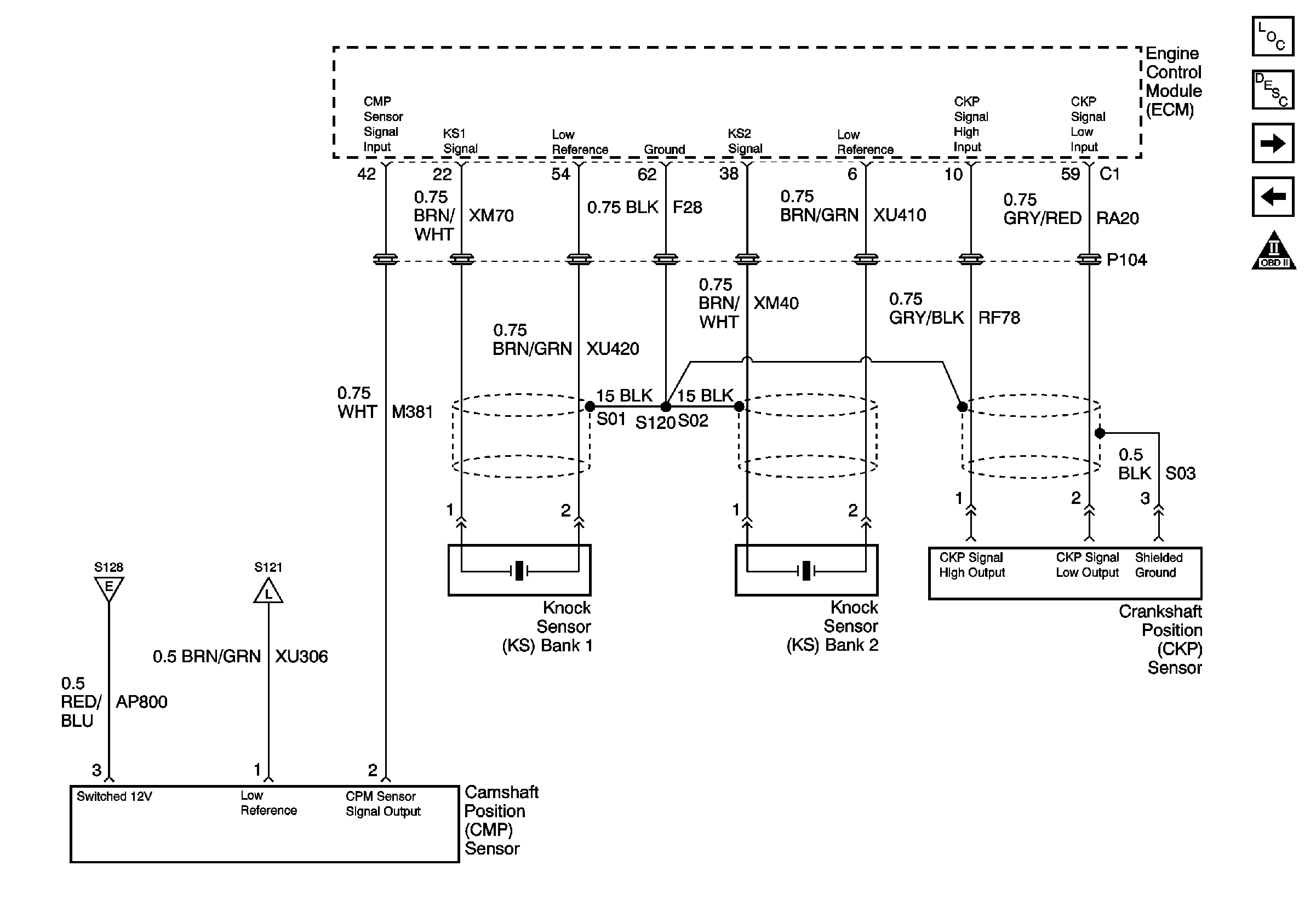

Object Number: 788043  Size: FS
Master Electrical Component List
Electronic Ignition (EI) System Description
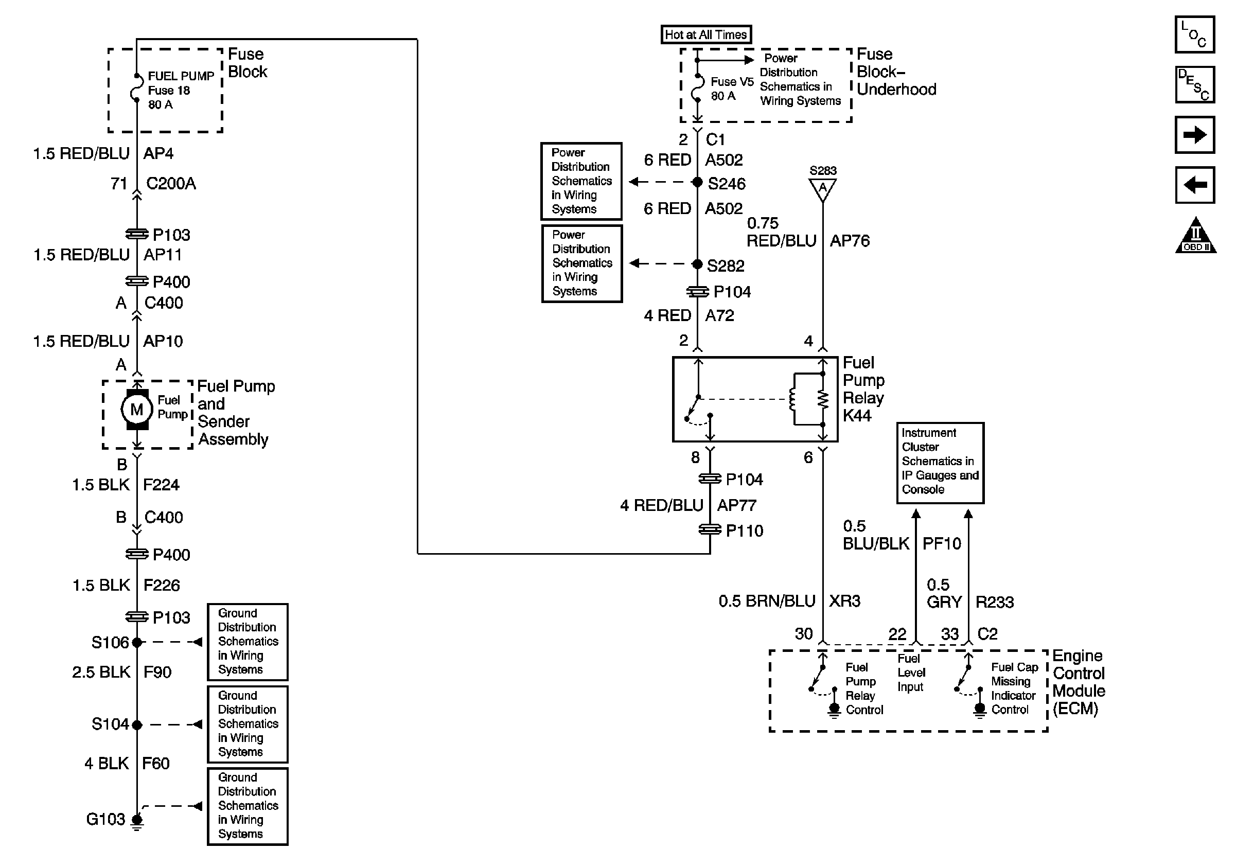
Fuel Controls - Fuel Pump
Ignition Controls - Ignition Coils
Engine Controls Schematic Icons
Engine Controls Power Relay
Engine Data Sensors - Pressure and Temperature
Figure 9:

Fuel Controls and Fuel Pump


Object Number: 788044  Size: FS
Master Electrical Component List
Fuel System Description
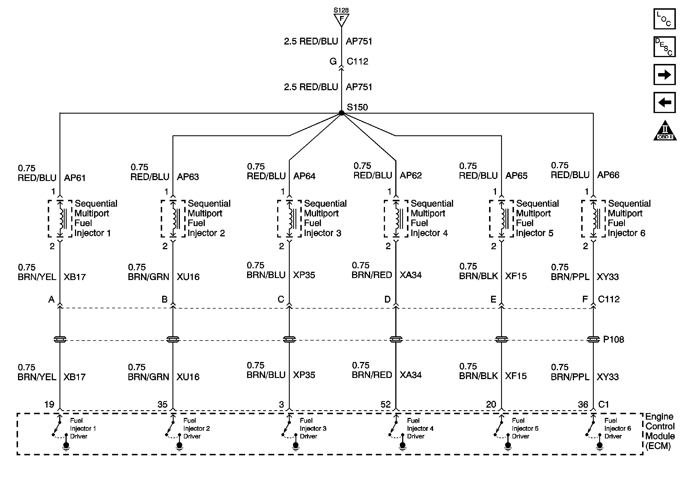
Fuel Controls - Fuel Injectors
Ignition Controls - Sensors
Engine Controls Schematic Icons
Battery Cable Bus
Underhood Fuse Block Fuse V5 and Fuse Block Fuses 6, 7, 20, and 25
Engine Controls Power Relay
Fuse Block Fuses 4, 18, and Engine Controls Power Relay
Fuel, Coolant and Oil Gauges and Indicators
G103 (5 of 8)
G103 (3 of 8)
G103 (1 of 8)
Figure 10:

Fuel Injectors


Object Number: 788046  Size: FS
Master Electrical Component List
Fuel System Description
Fuel Controls - EVAP Controls
Fuel Controls - Fuel Pump
Engine Controls Schematic Icons
Engine Controls Power Relay
Figure 11:

Fuel Tank Pressure (FTP) Sensor, Evaporative Vent Valve (EVAP) Solenoid, and Evaporative (EVAP) Purge Solenoid
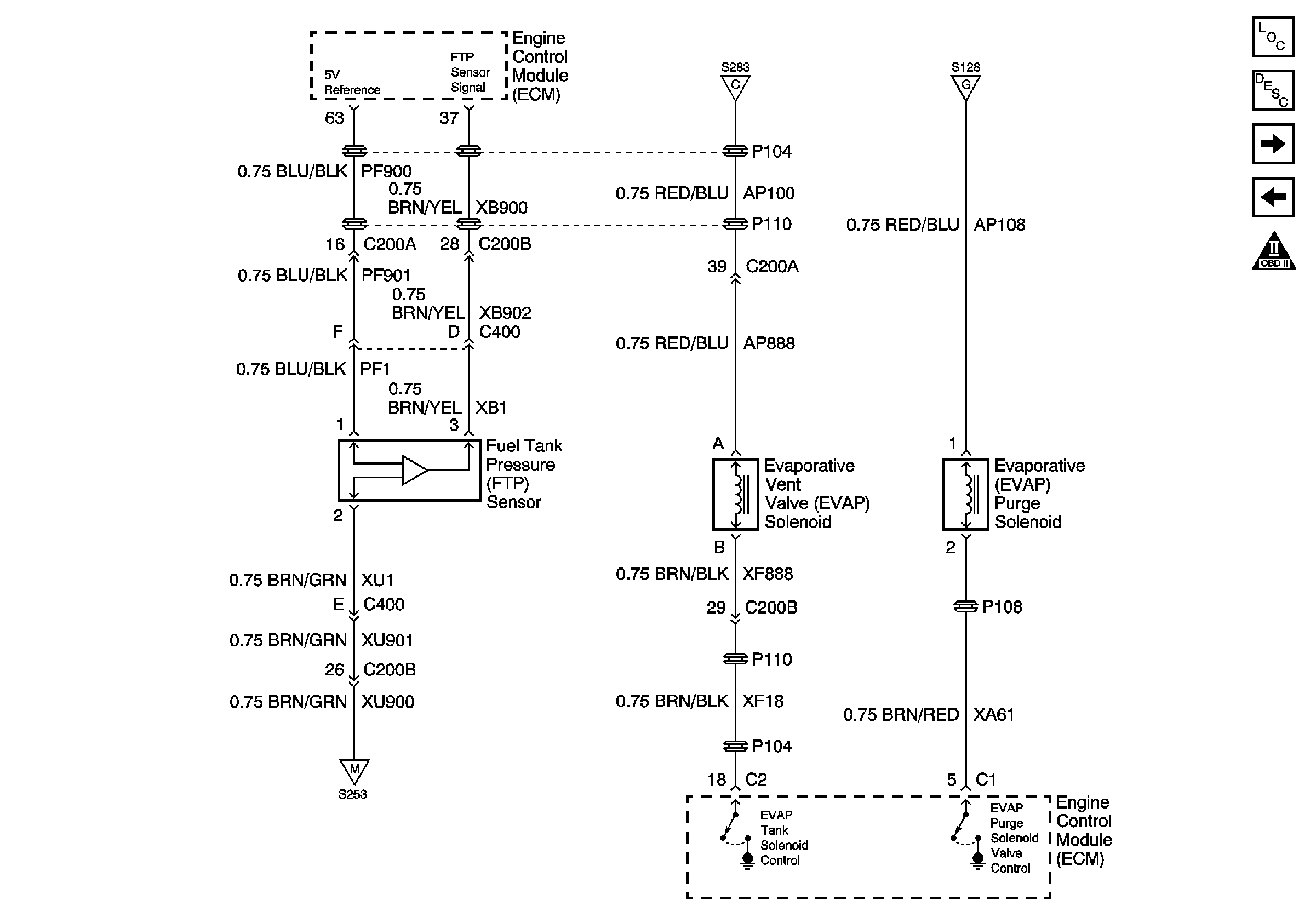

Object Number: 788048  Size: FS
Master Electrical Component List
Evaporative Emission Control System Description
Device Controls - AIR Injection and Intake Air Controls
Fuel Controls - Fuel Injectors
Engine Controls Schematic Icons
Engine Controls Power Relay
Engine Data Sensors - APP Sensor
Figure 12:

Air Injection and Intake (AIR) Solenoids
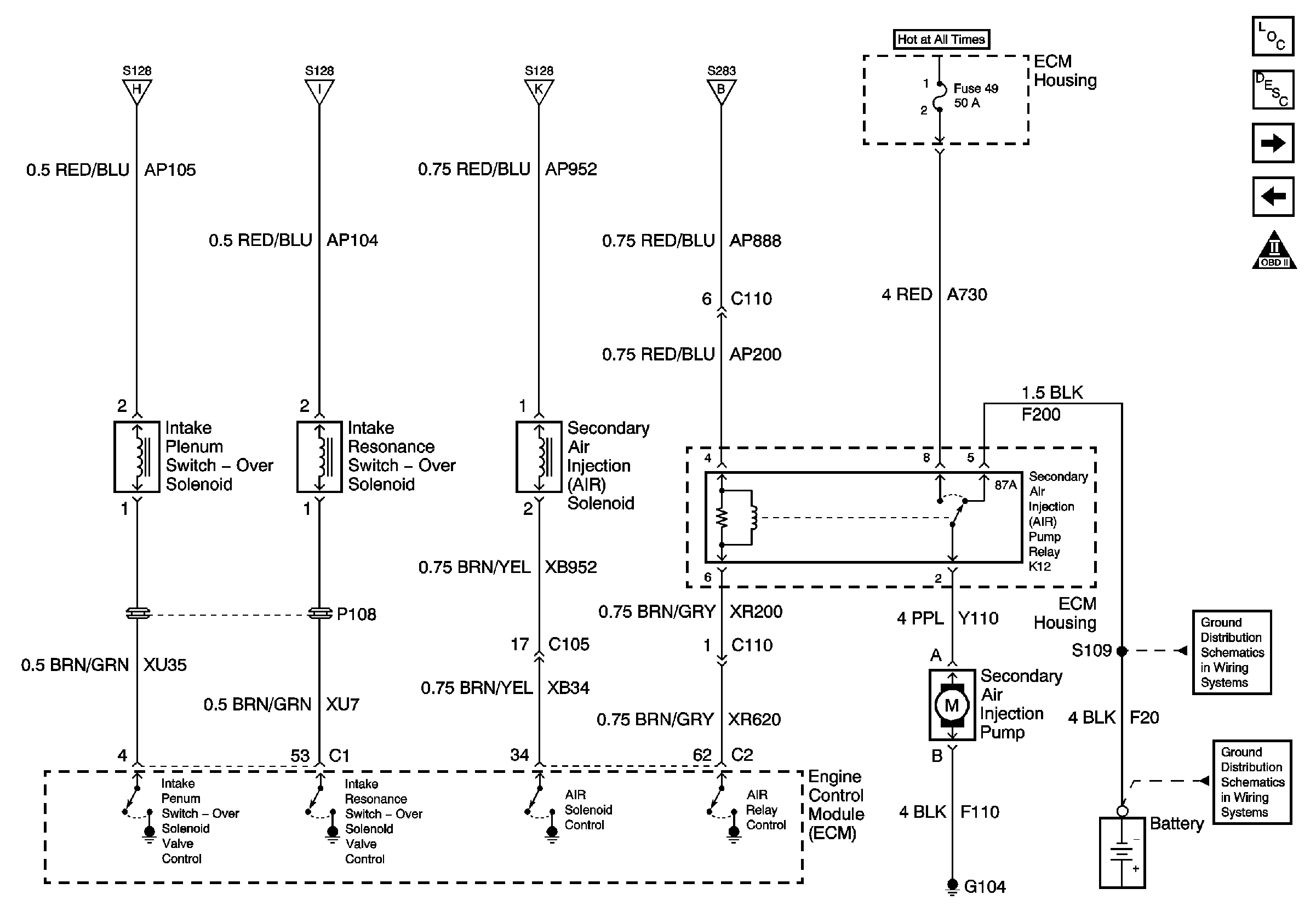

Object Number: 788049  Size: FS
Master Electrical Component List
Secondary Air Injection System Description
Controlled/Monitored Subsystem References
Fuel Controls - EVAP Controls
Engine Controls Schematic Icons
Engine Controls Power Relay
Battery Cable Bus
G103 (2 of 8)
G103 (1 of 8)
Figure 13:

Monitored/Controlled Subsystem References
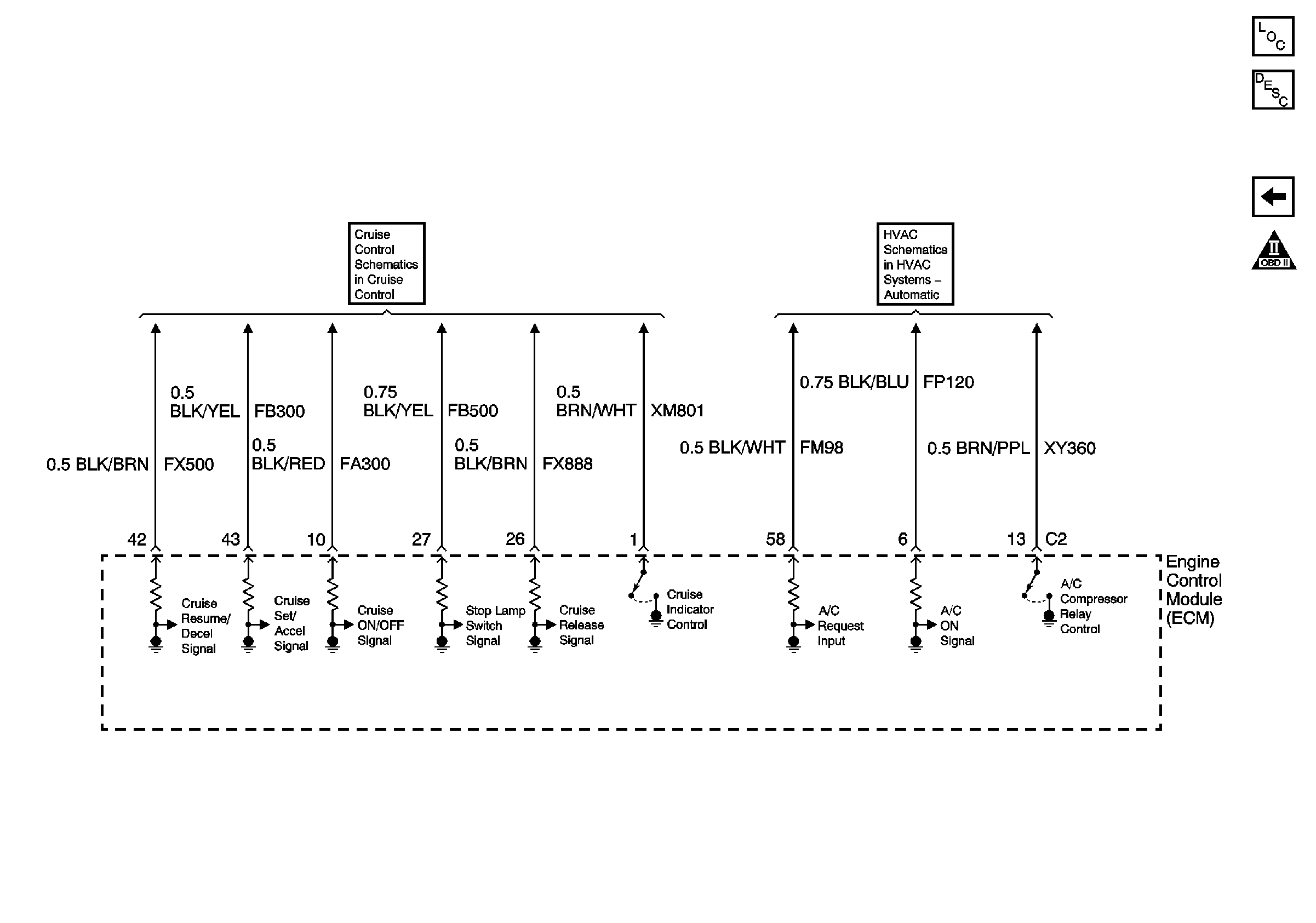

Object Number: 788051  Size: FS
Master Electrical Component List
Engine Control Module Description
Device Controls - AIR Injection and Intake Air Controls
Engine Controls Schematic Icons
Cruise Control Schematics
Compressor Controls