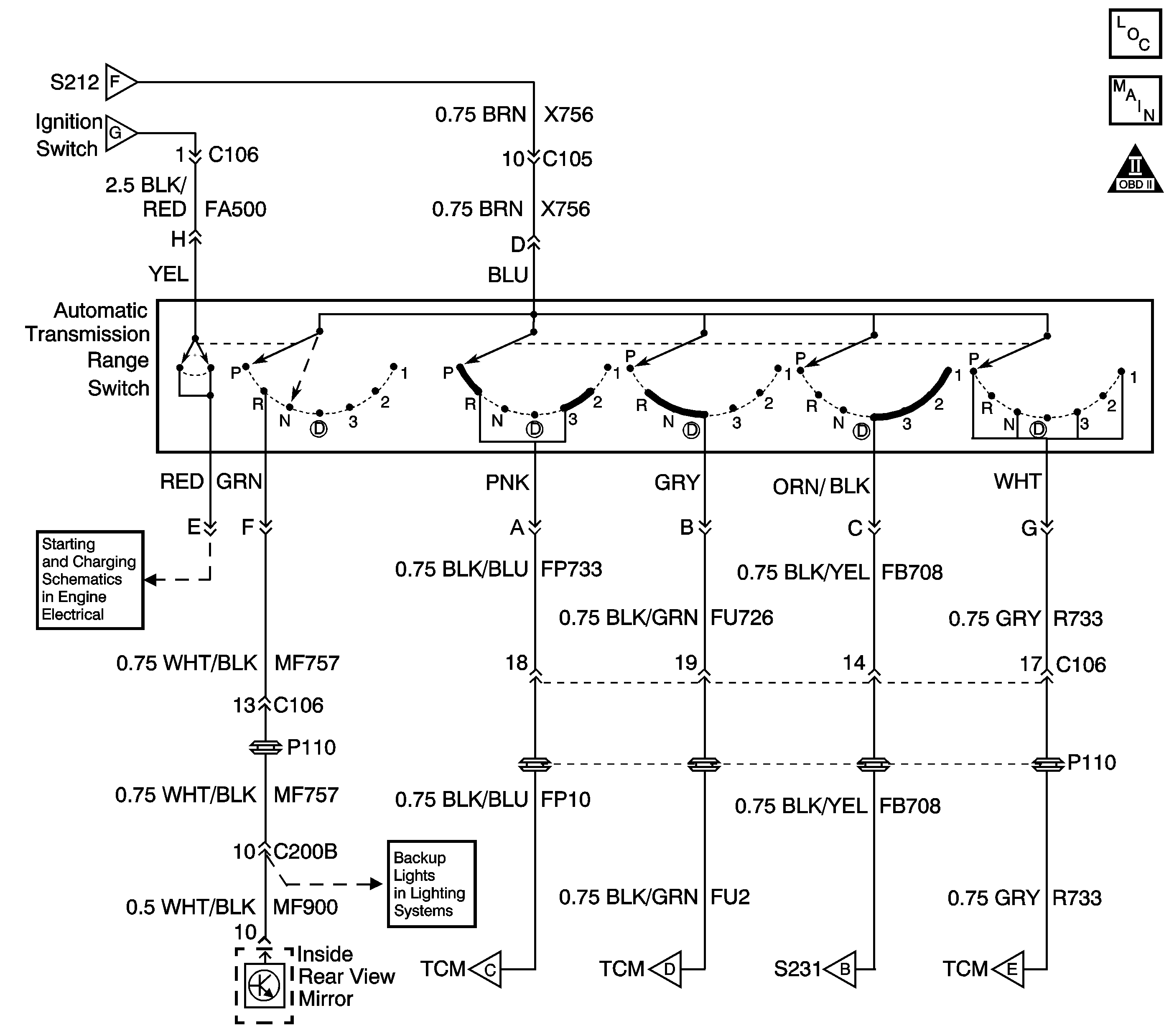
Circuit Description
The AT manual shaft shift position switch is attached externally to the left side of the 4L30-E transmission. The AT manual shaft shift position switch informs the transmission control module (TCM) and the console gear position indicator which gear the driver selects.
Ignition voltage is supplied to the switch on terminal D. Depending on the selector lever position, the ignition voltage connects to various combinations of terminals A, B, C, and G of the AT manual shaft shift position switch. The TCM decodes these combinations in order to determine gear selector lever position. Refer to the Automatic Transmission Manual Shift Shaft Position Switch Logic Table . When the TCM detects an electrical fault or an invalid state, DTC P0705 will set. DTC P0705 is a type B DTC.
Condition for Running the DTC
The ignition is ON.
Condition for Setting the DTC
The switch indicates an undefined or illegal gear position for 20 seconds.
Action Taken When the DTC Sets
| • | The TCM flashes the sport mode lamp and sends a MIL request to the ECM on the second consecutive drive trip that the diagnostic runs and fails. The ECM then illuminates the MIL. |
| • | The ECM records the operating conditions in the Freeze Frame at the time of the MIL request from the TCM. |
| • | The transmission operates in the default mode (maximum line pressure, command 4th gear, inhibit TCC, freeze shift adapts). |
Conditions For Clearing the MIL/DTC
| • | The ECM turns off the MIL after three consecutive drive trips during which the TCM sends no MIL request. |
| • | A History DTC clears after forty consecutive warm-up cycles, if no failures are present by this diagnostic or any other emission related diagnostic. |
| • | The scan tool clears the MIL/DTC. |
| • | The TCM cancels the DTC default mode actions when the ignition switch is Off long enough in order to power down the TCM. |
Diagnostic Aids
Refer to the Automatic Transmission Manual Shift Shaft Position Switch Logic Table
Test Description
The numbers below refer to the step numbers on the Diagnostic Table.
-
The Scan Tool display should match the selector lever position at each detent. If the lever has to be moved slightly within a position to get the right indication on theScan Tool , the AT manual shaft shift position switch adjustment should be checked. Refer to Manual Shift Shaft Position Switch Replacement .
-
Terminal D on the transmission harness side can be used as the power source.
Step | Action | Value(s) | Yes | No | ||||||||||||||
|---|---|---|---|---|---|---|---|---|---|---|---|---|---|---|---|---|---|---|
1 | Did you perform Powertrain On Board Diagnostic (OBD) System Check - Automatic Transmission ? | -- | Go to Powertrain On Board Diagnostic (OBD) System Check - Automatic Transmission | |||||||||||||||
Does the Scan Tool display agree with the selector lever in all of the positions? | P, R, N, D, 3, 2, 1 | Go to Intermittent Conditions in Engine Controls | ||||||||||||||||
3 | Does the Scan Tool display Drive in all selector lever positions? | -- | ||||||||||||||||
Does the test light illuminate? | -- | |||||||||||||||||
5 |
Important: The following step may also be performed using a J 39200 to measure circuit continuity or resistance. Instead of supplying power to terminal D of the switch, place one lead of the J 39200 to terminal D and probe the remaining switch terminals with the other lead. J 39200 resistance readings should be 1.0 - 3.3 ohms for terminals indicated by ON and O.L. (out of limits) for terminals shown as OFF. Refer to the Automatic Transmission Manual Shift Shaft Position Switch Logic Table . Does the test light illuminate only on the terminals indicated by ON in the table? | -- | ||||||||||||||||
6 |
Caution: When you are performing service on or near the SIR components or the SIR wiring, you must disable the SIR system. Refer to Disabling the SIR System. Failure to follow the correct procedure could cause air bag deployment, personal injury, or unnecessary SIR system repairs.
Did the test light illuminate on the proper terminals in each gear position? | -- | ||||||||||||||||
7 | Repair the ignition feed circuit to the AT manual shaft shift position switch. Did you complete the repair? | -- | -- | |||||||||||||||
8 | Test the AT manual shaft shift position switch harness connector for an incomplete connection or inadequate terminal tension. Refer to Testing for Intermittent Conditions and Poor Connections in Wiring Systems. Did you find and correct a condition? | -- | ||||||||||||||||
9 | Test the affected circuit(s) for the following conditions and repair as necessary:
Is the action complete? | -- | -- | |||||||||||||||
10 | Inspect the AT manual shaft shift position switch and shift control linkage for proper adjustment. Refer to Shift Control Linkage Adjustment . Did you find and correct a condition? | -- | ||||||||||||||||
11 | Replace the AT manual shaft shift position switch. Refer to Manual Shift Shaft Position Switch Replacement . Did you complete the replacement? | -- | -- | |||||||||||||||
12 |
Caution: When you are performing service on or near the SIR components or the SIR wiring, you must disable the SIR system. Refer to Disabling the SIR System. Failure to follow the correct procedure could cause air bag deployment, personal injury, or unnecessary SIR system repairs. Replace the TCM. Refer to Transmission Control Module Replacement . Did you complete the replacement? | -- | -- | |||||||||||||||
13 | Perform the following procedure in order to verify the repair:
Does the Scan Tool Trans Range match the gear selector in all positions? | -- | System OK |
