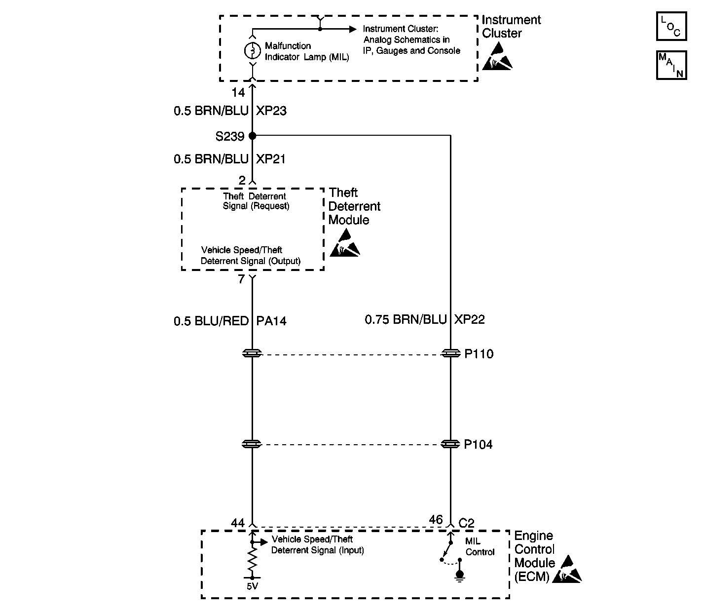
Circuit Description
The Theft Deterrent Module (Immobilizer) uses terminal 7 to send the vehicle speed signal and the frequency code (imo signal) to terminal 79 of the Engine Control Module (ECM).
When the ignition switch is turned to the ON position, a signal (transponder code) from the key is transmitted to the Theft Deterrent Module (TDM). During this period the ECM transmits a signal to the TDM requesting the frequency code (imo signal). The TDM compares the signal from the key and decides if an authorized key is being used. After verification, the TDM internally switches from the speed signal circuit and sends the imo signal to the ECM.
The ECM compares the received imo signal with the programmed stored signal. If both codes are the same, the engine control functions (fuel pump drive and injector signals) are released. Non matching codes block the engine functions and the car cannot be started.
Conditions for Setting the DTC
| • | DTC 16 indicates that a short to voltage exists in the speed/imo signal circuit (PA14). |
| • | The above conditions must be fulfilled for at least 0.51 seconds. |
Action Taken When the DTC Sets
| • | The engine starts then stalls. |
| • | The Theft Deterrent Module stores a DTC 16 in memory. |
Conditions for Clearing the DTC
| • | The conditions for the fault are no longer present. |
| • | A history DTC will clear after 20 consecutive ignition cycles if the condition for the fault is no longer present. |
| • | The use of the scan tool. |
Diagnostic Aids
Check the following conditions if a history or intermittent DTC is indicated:
| • | A poor connection at the TDM or ECM. Inspect the wiring harness connectors for backed out terminals, improper mating, improperly formed or damaged terminals, and poor terminal to wire connections. |
| • | A damaged wiring harness. Inspect the wiring harness for damage. If the wiring harness appears to be in good condition, observe the display on the DMM while moving the connectors and wiring harnesses related to the TDM and ECM. |
| • | For additional information, refer to Inducing Intermittent Fault Conditions in Wiring Systems. |
Test Description
The following numbers refer to the step numbers on the diagnostic table:
-
This step tests the circuit for a short to voltage.
-
Because no circuit condition was found, replace the module to remedy the condition.
Step | Action | Value(s) | Yes | No |
|---|---|---|---|---|
1 | Did you perform the Theft Deterrent Diagnostic System Check? | -- | Go to Step 2 | |
Test the vehicle speed/imo signal circuit for a short to voltage. Refer to Testing for a Short to Voltage in Wiring Systems. Did you find and correct the condition? | -- | Go to Step 3 | Go to Step 4 | |
3 |
Does the DTC reset? | -- | Go to Diagnostic Aids | System OK |
4 | Inspect for poor connections at the theft deterrent module connector terminal 7 and engine control module (ECM) connector C2 terminal 44. Refer to Testing for Intermittent Conditions and Poor Connections in Wiring Systems. Did you find and correct the condition? | -- | Go to Step 3 | Go to Step 5 |
Replace the theft deterrent module. Did you complete the replacement? | -- | Go to Step 3 | -- |
