Circuit Description
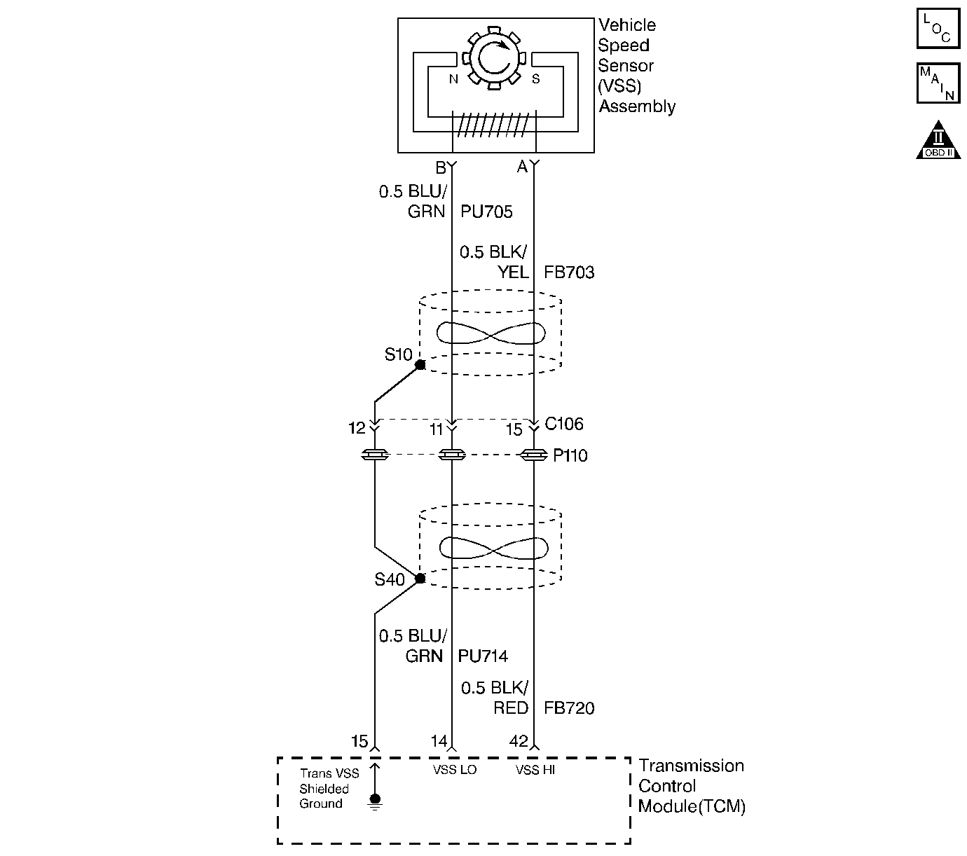
The vehicle speed sensor (VSS) assembly provides vehicle speed information to the transmission control module (TCM). The VSS assembly is a permanent magnet (PM) generator consisting of a reluctor wheel mounted on the output shaft and the VSS. The PM generator produces a pulsing AC voltage as the reluctor wheel teeth pass through the sensor's magnetic field. The AC voltage level and the number of pulses increase as the speed of the vehicle increases. The TCM converts the pulsing voltage to vehicle speed. The TCM uses the vehicle speed signal to determine shift timing and torque converter clutch (TCC) scheduling.
If the TCM detects no vehicle speed when there is engine speed in a drive gear range, then DTC P0722 sets. DTC P0722 is a type C DTC.
Conditions for Running the DTC
| • | The transmission is not in Park, Reverse or Neutral. |
| • | The engine speed is greater than 3008 RPM. |
Condition for Setting the DTC
The transmission output speed is 0 RPM.
Action Taken When the DTC Sets
| • | Early production - The TCM illuminates the service transmission lamp (STL) and sends a MIL request to the ECM on the second consecutive drive trip that the diagnostic runs and fails. The ECM then illuminates the MIL. |
| • | Late production - The TCM flashes the Sport Mode Lamp and sends a MIL request on the second consecutive drive trip that the diagnostic runs and fails. The TCM then illuminates the MIL. |
| • | The ECM records the operating conditions in the Freeze Frame at the time of the MIL request from the TCM. |
| • | The transmission operates in the default mode (maximum line pressure, command 4th gear, inhibit TCC, freeze shift adapts). |
Conditions for Clearing the MIL/DTC
| • | Early production - The TCM turns off the STL as soon as the fault is no longer present. |
| • | Late production - The TCM stops flashing the sport mode lamp as soon as the fault is no longer present. |
| • | The ECM turns off the MIL after three consecutive drive trips during which the TCM sends no MIL request. |
| • | A History DTC clears after forty consecutive warm-up cycles, if no failures are present by this diagnostic or any other emission related diagnostic. |
| • | The scan tool clears the MIL/DTC. |
| • | The TCM cancels the DTC default mode actions when the fault no longer exists and the ignition switch is Off long enough in order to power down the TCM. |
Diagnostic Aids
Vehicles equipped with Fuel Cap Lamps utilize the Sport Mode lamp to indicate a transmission malfunction. In these vehicles, the Sport Mode Lamp flashes at 200 millisecond intervals when the TCM commands the lamp ON.
Vehicles not equipped with Fuel Cap Lamps are equipped with a dedicated Service Transmission Lamp (STL) on the Instrument Panel Cluster (IPC). The STL illuminates steadily when the TCM commands the lamp ON.
Use the J 35616-A connector test adapter kit for any test that requires probing the TCM harness connector or a component harness connector. Using this kit will prevent damage to the harness connector terminals.
Check for the following conditions:
| • | Poor connections at the TCM or at the component. Inspect the harness connectors for any backed out terminals, improper mating, broken locks, improperly formed or damaged terminals, and poor terminal to wire connection. |
| Refer to General Electrical Diagnosis in Wiring Systems for proper procedure. |
| • | Damaged harness. Inspect the wiring harness for damage. If the harness appears to be OK, observe the scan tool while moving any related connectors and any wiring harnesses. A change in the display may help to locate the fault. |
Test Description
The numbers below refer to the step numbers on the diagnostic table.
-
Disable the traction control system when performing this step.
-
This step tests the VSS assembly circuit.
-
This step tests the integrity of the VSS assembly.
Step | Action | Value(s) | Yes | No |
|---|---|---|---|---|
1 | Was the Powertrain On-Board Diagnostic (OBD) System Check performed? | -- | ||
Important: Before clearing the DTC, use the Scan Tool in order to record the Freeze Frame and Failure Records. Using the Clear Info function erases the freeze frame and Failure Records from the ECM/TCM. With the drive wheels rotating, does the Scan Tool Transmission OSS increase with the drive wheel speed? | -- | Go to Diagnostic Aids | ||
Is the resistance within the specified range? | 2750-3770 ohms | |||
4 | Measure the resistance from terminal 42 to a known good ground. Is the resistance greater than the specified value? | 50 K ohms | ||
By vigorously rotating the wheel by hand can a voltage greater than the specified value be obtained? | 0.5 volts AC | |||
6 |
Is the resistance within the specified range? | 2750-3770 ohms | ||
7 | Inspect circuits FB 703 (BLK/YEL) and PU 705 (BLU/GRN) for a short to ground. Refer to General Electrical Diagnosis in Wiring Systems. Did you find a short to ground? | -- | Go to Diagnostic Aids | |
8 | Inspect circuits FB 703 (BLK/YEL) and PU 705 (BLU/GRN) for an open. Refer to General Electrical Diagnosis in Wiring Systems. Did you find an open? | -- | Go to Diagnostic Aids | |
9 | Make the necessary wiring repairs. Refer to Wiring Repairs in Wiring Systems. Is the repair complete? | -- | -- | |
10 | Repair or replace the VSS reluctor wheel. Refer to Case Extension and Gasket Replacement . Is the repair complete? | -- | -- | |
11 |
Did you find a condition? | -- | ||
12 | Replace the VSS. Refer to Vehicle Speed Sensor . Is the replacement complete? | -- | -- | |
13 | Replace the TCM. Refer to Transmission Control Module Replacement . Is the replacement complete? | -- | -- | |
14 | Perform the following procedure in order to verify the repair:
Does the Scan Tool display transmission output speed? | -- | System OK |
