Circuit Description
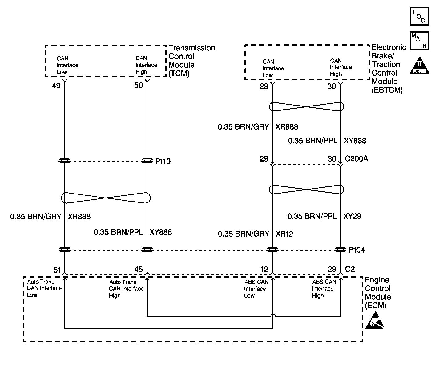
The Controller Area Network (CAN) serial data circuit is a high speed serial data bus used to communicate information between the Electronic Brake and Traction Control Module (EBTCM), the Engine Control Module (ECM) and the Transmission Control Module (TCM). When the ignition switch is turned to the ON position, the modules begin to transmit data between each other. The following data is transmitted and received between the ECM and TCM:
| • | Brake Switch signal from the ECM to the TCM |
| • | Throttle Position Angle from the ECM to the TCM |
| • | Engine Speed signal from the ECM to the TCM |
| • | Engine Coolant Temperature from the ECM to the TCM |
| • | Engine Torque signal from the ECM to the TCM |
| • | MIL Request signal from the TCM to the ECM |
The following data is transmitted and received between the ECM and EBTCM:
| • | Requested Torque from the EBTCM to the ECM |
| • | Delivered Torque from the ECM to the EBTCM |
| • | Engine Speed (RPM) from the ECM to the EBTCM |
The addressing scheme employed with CAN assigns a label to every message, with each message receiving a unique "identifier". The identifier classifies the content of the message (such as engine speed). Each module processes only those messages whose identifiers are stored in the module's acceptance list. This is CAN's form of message filtering.
The identifier labels both the data content and the priority of the message being sent. Each module can begin transmitting its most important data as soon as the bus is unoccupied. When more than one module starts to transmit simultaneously, the message with the highest priority is assigned first access. A module responds to failure to gain access by automatically switching to receive mode, the module then repeats the transmission attempt as soon as the bus is free again.
Conditions for Running the DTC
The CAN Bus circuit is monitored continuously after the ignition switch is turned to the ON position.
Conditions for Setting the DTC
Each controller on the CAN Bus monitors the activity or traffic on the bus. The control module that has set the code has detected that there is no activity or traffic on the bus. This indicates that there may be fewer controllers actively communicating on the bus than programmed.
Action Taken When the DTC Sets
The following describes the action taken when the code is set in a particular control module.
Engine Control Module
| • | The Malfunction Indicator Lamp (MIL) is illuminated on the second consecutive drive trip that the diagnostic runs and fails. |
| • | The ECM records the operating conditions at the time the MIL is illuminated in the Freeze Frame. |
Electronic Brake Traction Control Module
| • | A malfunction DTC is stored for diagnostic purposes. |
| • | TCS remains active. |
| • | The TC indicator remains off for this DTC. |
Conditions for Clearing the MIL/DTC
The following describes the conditions for clearing the MIL/DTC in a particular control module.
Engine Control Module
| • | The condition for the DTC is no longer present. The ECM turns off the MIL after 3 consecutive drive trips that the diagnostic runs and passes. |
| • | The scan tool clear DTC function is used. |
| • | A history DTC clears after 40 consecutive warm-up cycles, if no failures are present by this diagnostic or any other emission related diagnostic. |
| • | The ECM battery voltage is interrupted. |
Electronic Brake Traction Control Module
| • | The condition for the DTC is no longer present. |
| • | The scan tool clear DTC function is used. |
| • | A history DTC clears after 100 ignition cycles pass with no malfunction detected. |
Diagnostic Aids
This DTC is confined to a malfunction with the control module that the DTC was set in, or the control module(s) that is connected to the module the code was set in. A physical malfunction of the harness is not the cause of this DTC. If there is a malfunction with the CAN Bus harness, DTC U2100 will be set.
The scan tool can be used as an aid in diagnosing this DTC. In the scan tool data display, observe the following parameters that are transmitted over the CAN Bus:
Engine Data Display
MIL Request
Transmission Data Display
| • | Brake Switch |
| • | Engine Coolant Temperature (ECT) |
| • | Engine Speed |
| • | Engine Torque |
| • | Throttle Position (TP) Angle |
ABS Data Display
| • | Engine Speed |
| • | Delivered Engine Torque |
Observing the data display parameters for abnormalities or missing data may pinpoint which control module is causing the malfunction.
Test Description
The number(s) below refer to the step number(s) on the diagnostic table.
-
A DTC U2100 set in either the ECM, TCM or EBTCM may have caused U2103 to set. You must diagnose and clear DTC U2100 to determine if it is the cause of U2103 setting.
-
A U2105, U2106 or U2108 DTC with a history status may indicate the cause of U2103.
-
The module(s) which are not communicating data is the likely cause of U2103 being set.
-
The module(s) which was not communicating data due to a poor connection to the CAN Bus circuit may have set other CAN Bus codes for the bus or modules that it was monitoring.
-
The modules which can communicate indicate the module which cannot communicate. You must clear the DTC from these modules to avoid future misdiagnosis.
-
If all modules are communicating, the module which set U2103 may have done so due to some other condition.
-
The module which set U2103 is the likely cause of the malfunction.
Step | Action | Value(s) | Yes | No | ||||||||||||
|---|---|---|---|---|---|---|---|---|---|---|---|---|---|---|---|---|
1 | Was the Data Link Communications Diagnostic System Check performed? | -- | ||||||||||||||
Was DTC U2100 recorded as a history or current DTC in the ECM, TCM or EBTCM? | -- | Go to DTC U2100 CAN-BUS Communication Malfunction and perform the diagnostics for the DTC | ||||||||||||||
Were any of the following DTCs recorded with a history status?
| -- | Go to Diagnostic Trouble Code (DTC) List and perform the diagnostics for the applicable DTC | ||||||||||||||
Is any module on the CAN Bus not receiving data? | -- | |||||||||||||||
5 |
Did you find and correct the condition? | -- | ||||||||||||||
6 |
Did you find and correct the condition? | -- | ||||||||||||||
7 | Replace the Module(s) which are not communicating data. Refer to Engine Control Module Replacement/Programming in Engine Controls 3.0L or Transmission Control Module Replacement in Automatic Transmission 4L30-E or Electronic Brake and Traction Control Module Replacement in Antilock Brake System. Did you complete the replacement? | -- | -- | |||||||||||||
Does the scan tool display any DTCs other than the following?
| -- | Go to the applicable DTC Table | ||||||||||||||
9 | Clear DTCs using the Scan Tool Did you complete the action? | -- | -- | |||||||||||||
Does the scan tool display any DTCs other than the following?
| -- | Go to the applicable DTC Table | ||||||||||||||
11 | Clear DTCs using the scan tool. Did you complete the action? | -- | System OK | -- | ||||||||||||
Did you record any other DTCs for the module(s) which had U2103 set as a current DTC? | -- | Go to the applicable DTC Table | ||||||||||||||
Does the scan tool display DTC U2103 as a current DTC? | -- | System OK | ||||||||||||||
14 | Replace the module which had DTC U2103 set as a current DTC. Refer to Engine Control Module Replacement/Programming in Engine Controls 3.0L or Transmission Control Module Replacement in Automatic Transmission 4L30-E or Electronic Brake and Traction Control Module Replacement in Antilock Brake System. Did you complete the replacement? | -- | System OK | -- |
