GM Service Manual Online
For 1990-2009 cars only
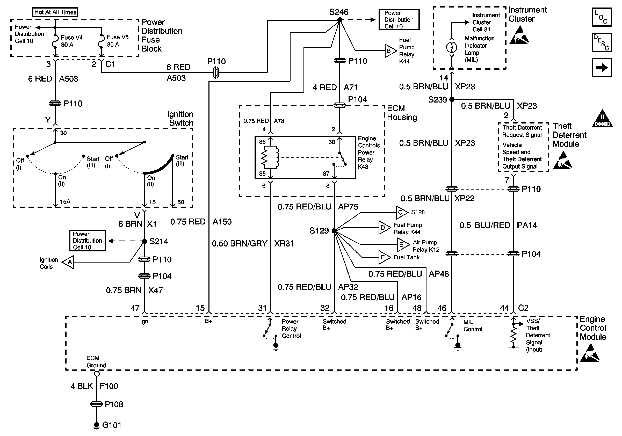
Figure 1:

Cell 20: Power, Ground, and MIL


Object Number: 361528  Size: FS
Engine Controls Components
Engine Control Module Description
Cell 20: DLC and CAN Interface
OBD II Symbol Description Notice
Handling ESD Sensitive Parts Notice
Power Distribution Schematics
Cell 20: Ignition System
Power Distribution Schematics
Cell 20: Fuel Controls
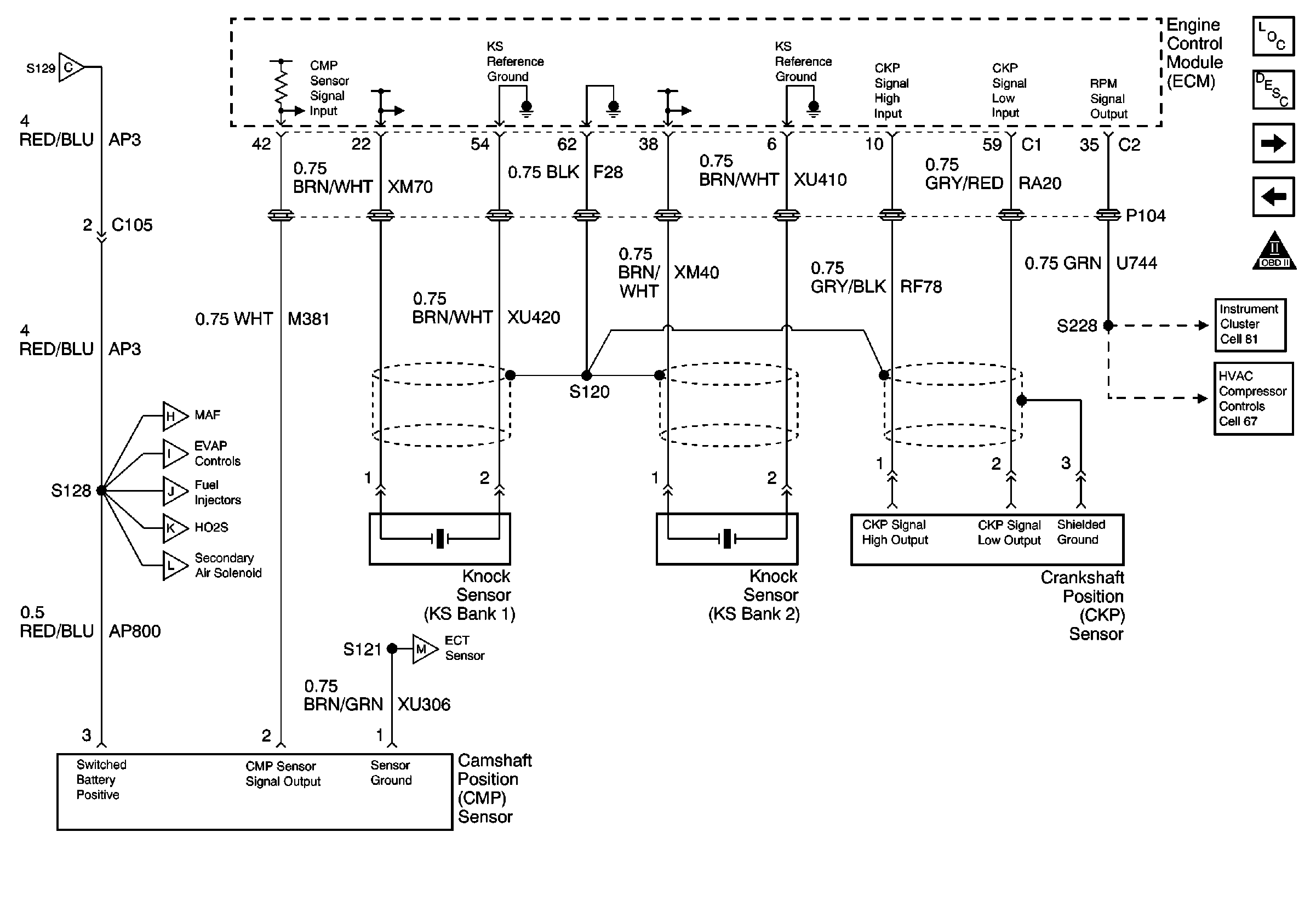
Cell 20: Engine Data Sensors
Cell 20: Fuel Controls
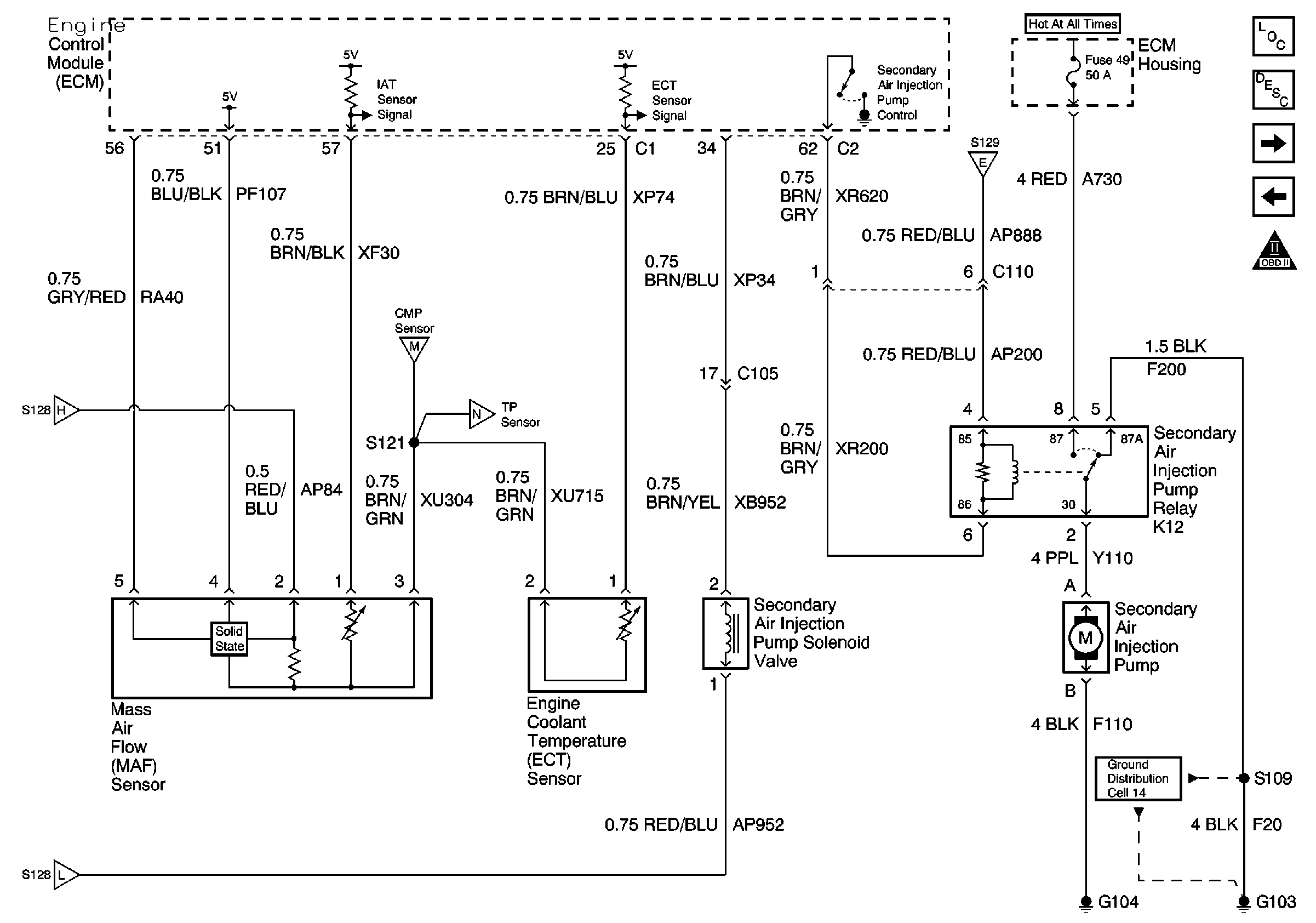
Cell 20: Air Injection Pump, MAF and ECT Sensors
Cell 20: EVAP Tank, Purge and Intake Plenum, Resonance Sol. Valves
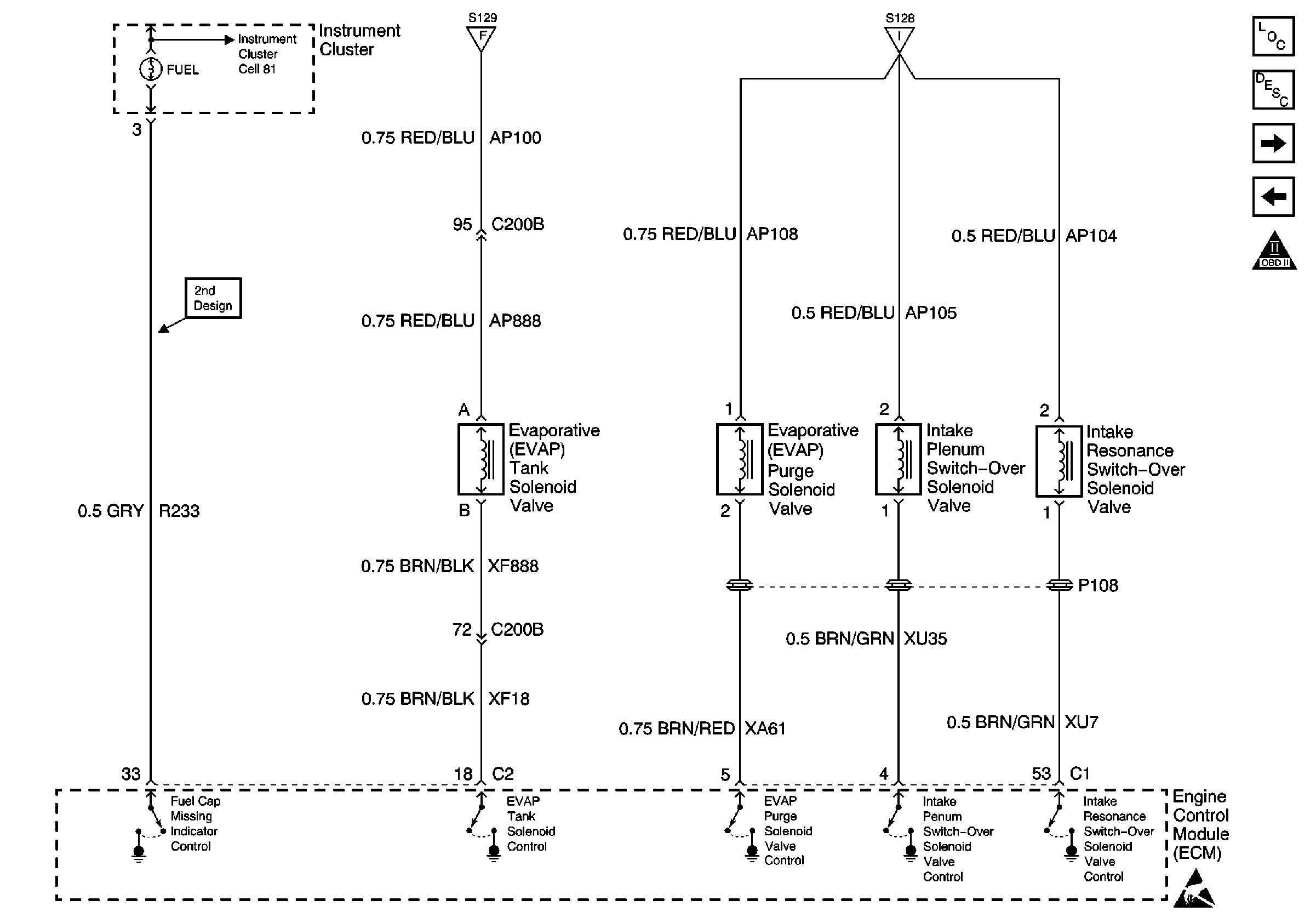
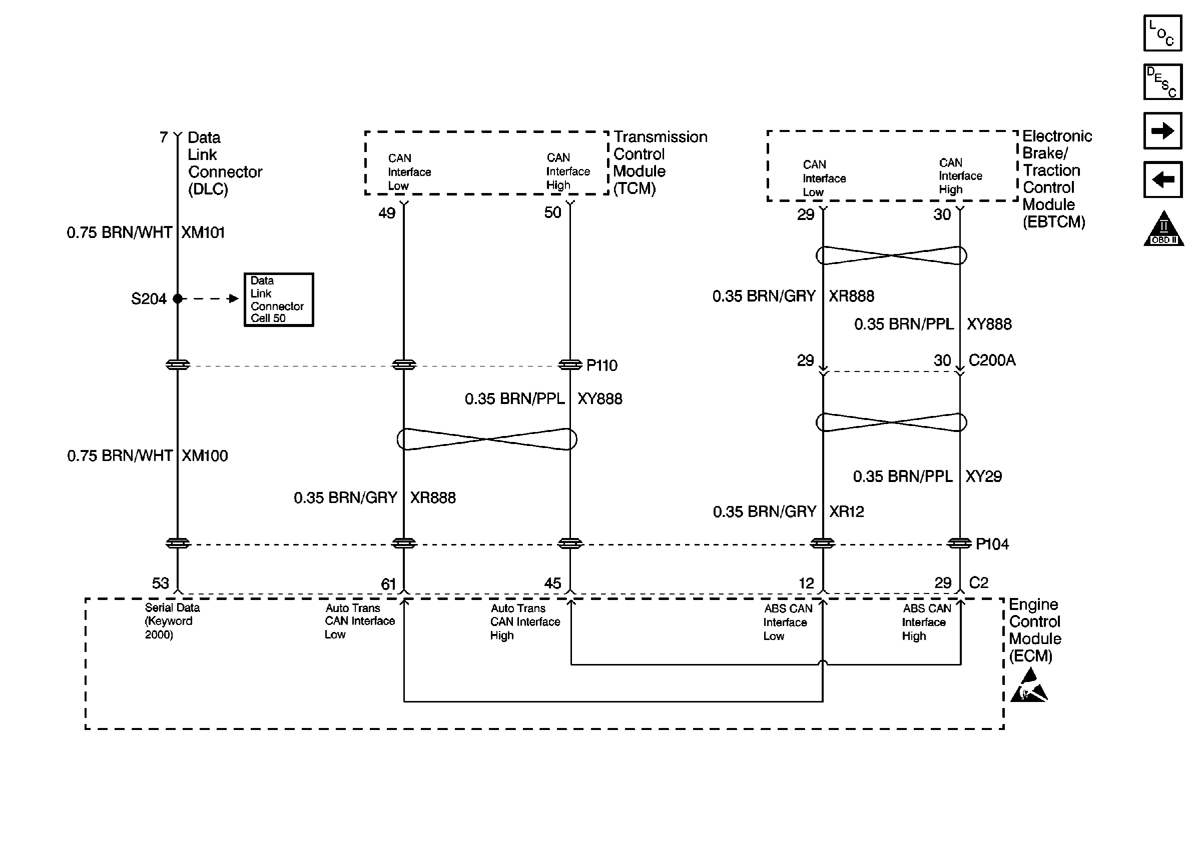
Figure 2:

Cell 20: DLC and CAN Interface


Object Number: 443806  Size: FS
Engine Controls Components
Serial Data Communications
Cell 20: Ignition System
Cell 20: Power, Ground, and MIL
OBD II Symbol Description Notice
Handling ESD Sensitive Parts Notice
Cell 50 Sun Roof Actuator, TCM, ECM, and Instrument Cluster
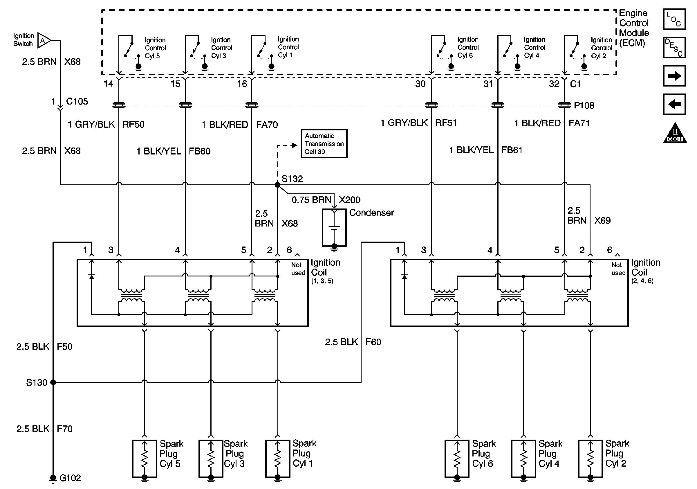
Figure 3:

Cell 20: Ignition System


Object Number: 361542  Size: FS
Engine Controls Components
Electronic Ignition (EI) System Description
Cell 20: Fuel Controls
Cell 20: DLC and CAN Interface
OBD II Symbol Description Notice
Cell 20: Power, Ground, and MIL
Automatic Transmission Controls Schematics
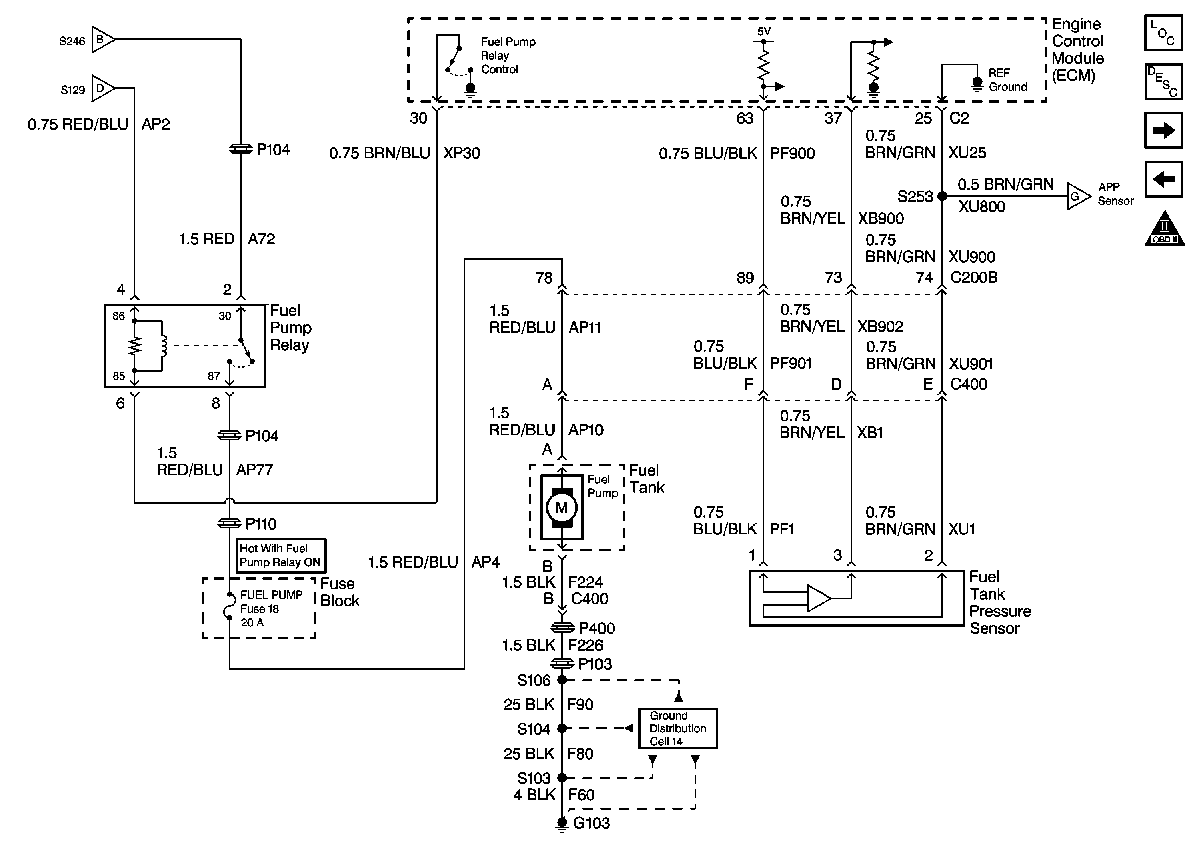
Figure 4:

Cell 20: Fuel Controls


Object Number: 361544  Size: FS
Engine Controls Components
Fuel Supply Component Description
Cell 20: Engine Data Sensors
Cell 20: Ignition System
Engine Controls Schematic Icons
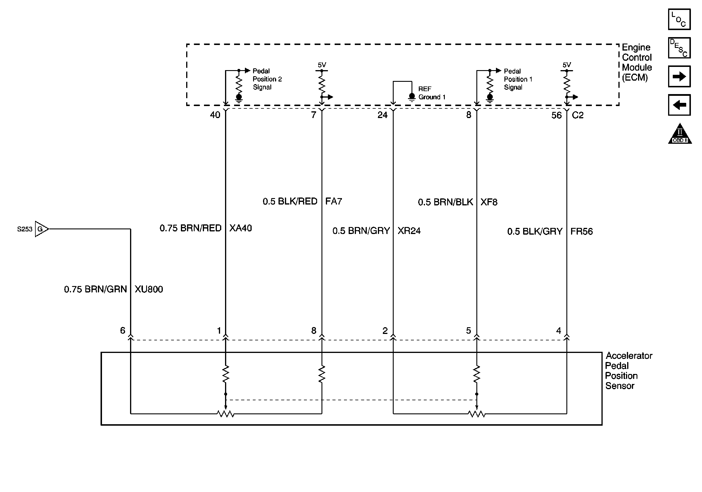
Cell 20: Accelerator Pedal Position (APP) Sensor
Cell 20: Power, Ground, and MIL
Ground Distribution Schematics
Figure 5:

Cell 20: Engine Data Sensors


Object Number: 361543  Size: FS
Engine Controls Components
Information Sensors
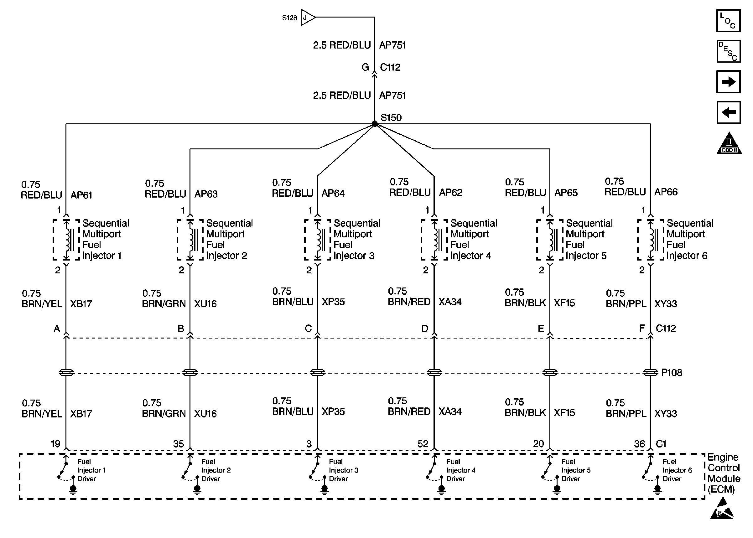
Cell 20: Fuel Injectors
Cell 20: Fuel Controls
Engine Controls Schematic Icons
Cell 81: Gauge Cluster Brake Pad Wear and Seat Belt Warning Indicators
Cell 67
Cell 20: Air Injection Pump, MAF and ECT Sensors
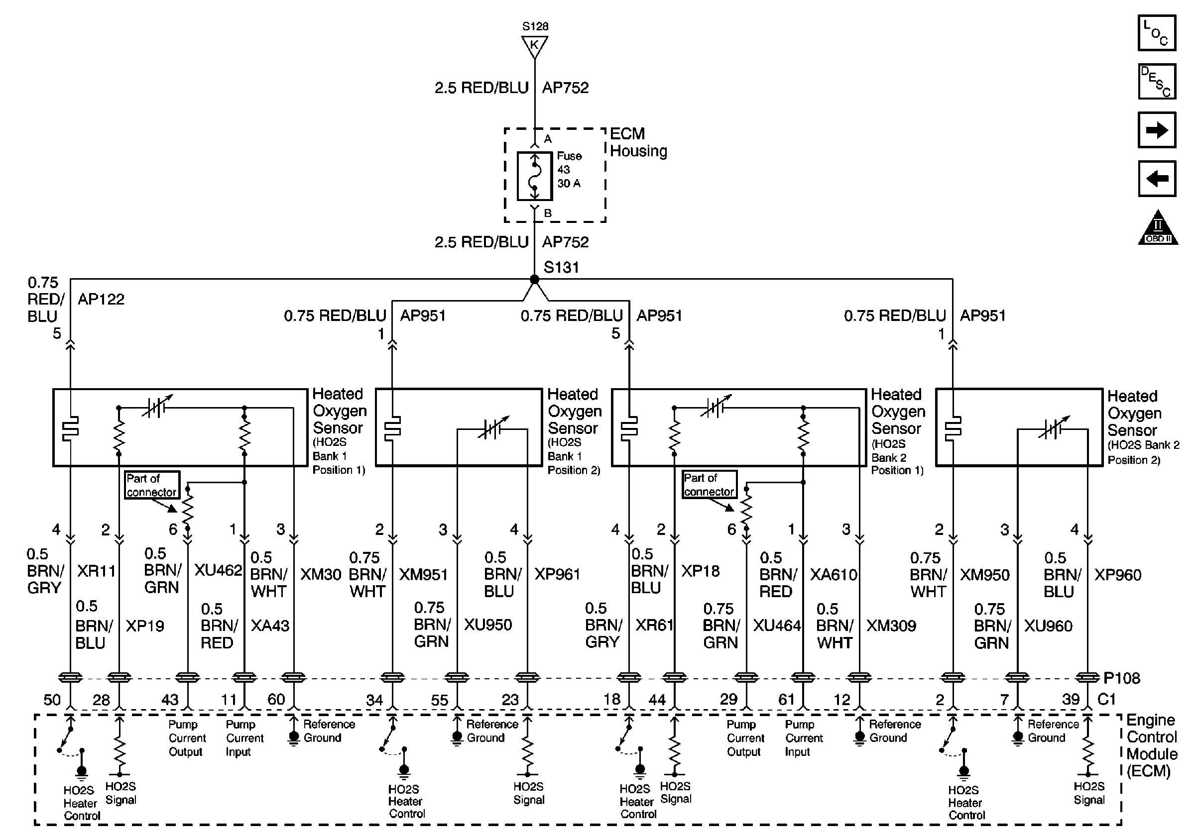
Cell 20: Heated Oxygen Sensors
Cell 20: Fuel Injectors
Cell 20: EVAP Tank, Purge and Intake Plenum, Resonance Sol. Valves
Cell 20: Air Injection Pump, MAF and ECT Sensors
Cell 20: Power, Ground, and MIL
Figure 6:

Cell 20: Fuel Injectors


Object Number: 361545  Size: FS
Engine Controls Components
Fuel Metering System Description
Cell 20: Air Injection Pump, MAF and ECT Sensors
Cell 20: Engine Data Sensors
Engine Controls Schematic Icons
Cell 20: Engine Data Sensors
Figure 7:

Cell 20: Air Injection Pump, MAF and ECT Sensors


Object Number: 361546  Size: FS
Engine Controls Components
Information Sensors
Cell 20: Heated Oxygen Sensors
Cell 20: Fuel Injectors
Engine Controls Schematic Icons
Ground Distribution Schematics
Cell 20: Power, Ground, and MIL
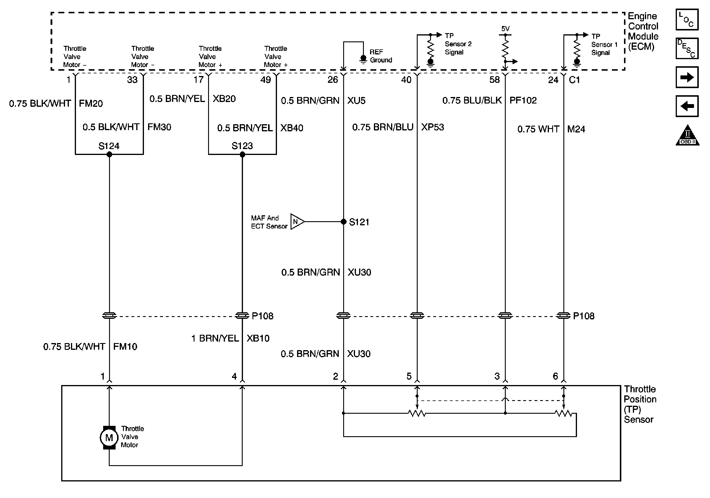
Cell 20: Throttle Position (TP) Sensor
Cell 20: Engine Data Sensors
Figure 8:

Cell 20: Heated Oxygen Sensors


Object Number: 365713  Size: FS
Engine Controls Components
Information Sensors
Cell 20: EVAP Tank, Purge and Intake Plenum, Resonance Sol. Valves
Cell 20: Air Injection Pump, MAF and ECT Sensors
Engine Controls Schematic Icons
Cell 20: Engine Data Sensors
Figure 9:

Cell 20: EVAP Tank, Purge and Intake Plenum, Resonance Sol. Valves


Object Number: 365716  Size: FS
Engine Controls Components
Evaporative Emission Control System Operation Description
Cell 20: Throttle Position (TP) Sensor
Cell 20: Heated Oxygen Sensors
Engine Controls Schematic Icons
Cell 20: Engine Data Sensors
Cell 20: Power, Ground, and MIL
Cell 81: Instrument Cluster Cruise, Airbag, MIL and A/T Malfunction Indicators
Figure 10:

Cell 20: Throttle Position (TP) Sensor


Object Number: 361547  Size: FS
Engine Controls Components
Information Sensors
Cell 20: Accelerator Pedal Position (APP) Sensor
Cell 20: EVAP Tank, Purge and Intake Plenum, Resonance Sol. Valves
Engine Controls Schematic Icons
Cell 20: Air Injection Pump, MAF and ECT Sensors
Figure 11:

Cell 20: Accelerator Pedal Position (APP) Sensor


Object Number: 363038  Size: FS
Engine Controls Components
Information Sensors
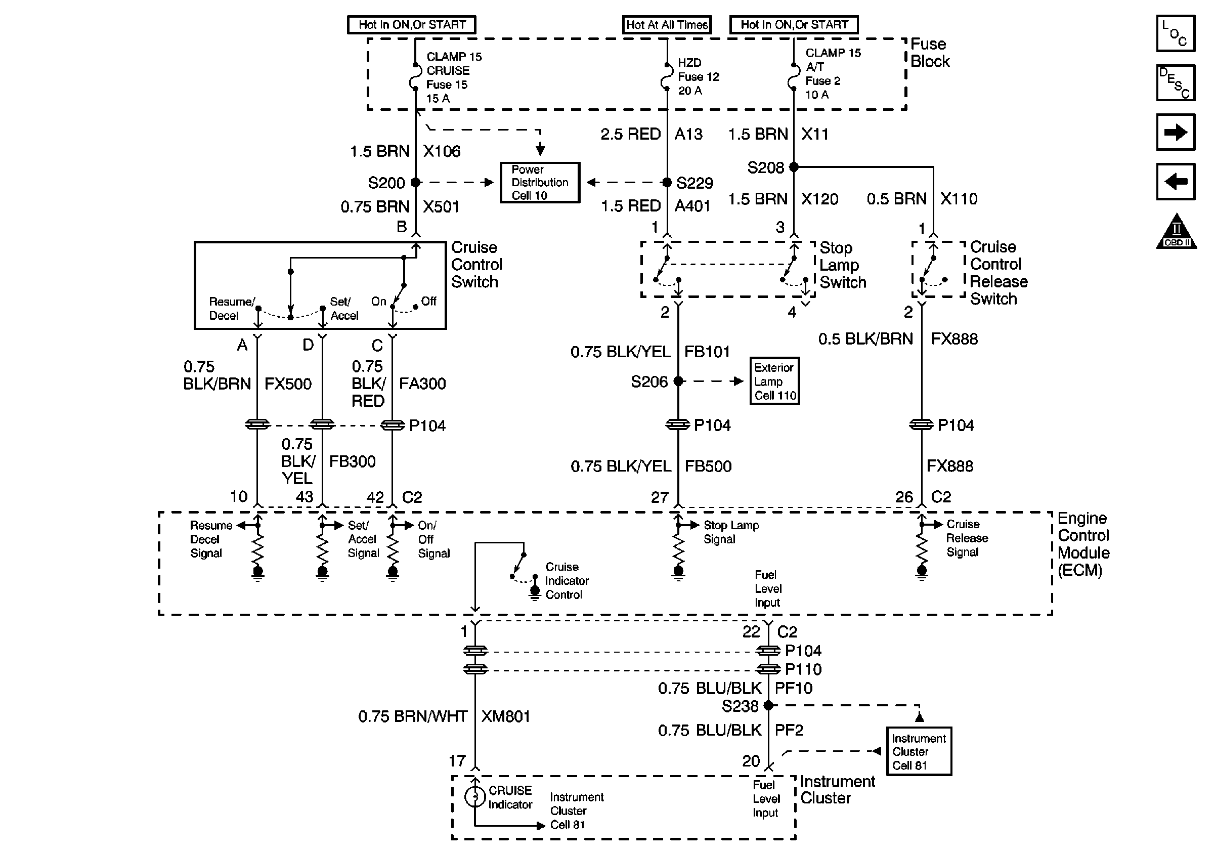
Cell 20: Cruise Control
Cell 20: Throttle Position (TP) Sensor
Engine Controls Schematic Icons
Cell 20: Fuel Controls
Figure 12:

Cell 20: Cruise Control


Object Number: 365718  Size: FS
Engine Controls Components
Cruise Control System Circuit Description
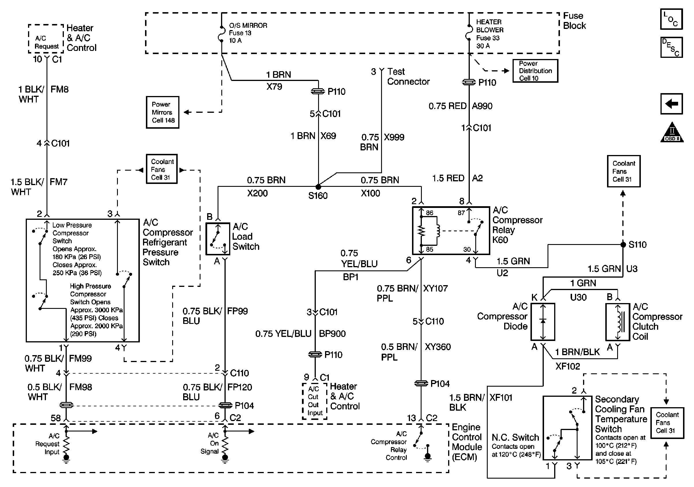
Cell 20: A/C Controls
Cell 20: Accelerator Pedal Position (APP) Sensor
Engine Controls Schematic Icons
Power Distribution Schematics
Cell 81: Instrument Cluster Coolant and Fuel Gauges
Cell 110 Cornering Lamps, Stop/Tailamps, Auxiliary Brake Lamp
Cell 81: Instrument Cluster Cruise, Airbag, MIL and A/T Malfunction Indicators
Figure 13:

Cell 20: A/C Controls


Object Number: 366529  Size: FS
Engine Controls Components
Air Conditioning (A/C) System Description
Cell 20: Cruise Control
Engine Controls Schematic Icons
Cell 10 Fuse Block, Turn Signal Switch, Blower Control, and A/C Compressor Relay
Cooling Fan, Auxiliary Water Pump, and Heater Water Auxiliary Pump
Coolant Level Indicator
Cell 147 Outside Remote Control Rear View Mirror Switch Without Memory
Coolant Level Indicator