Removal Procedure
- Remove the oil filler tube.
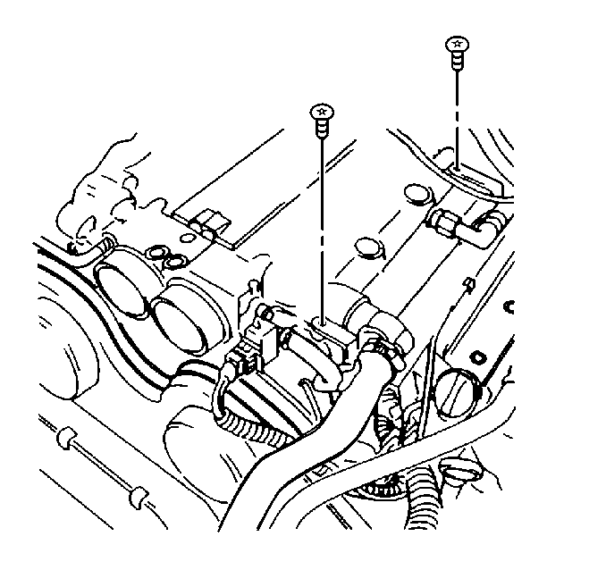
- Remove the A/C compressor hose bracket bolt from engine.
- Reposition the A/C compressor hose.
- Remove the bolts from wiring harness channel.
- Reposition the wiring harness channel.
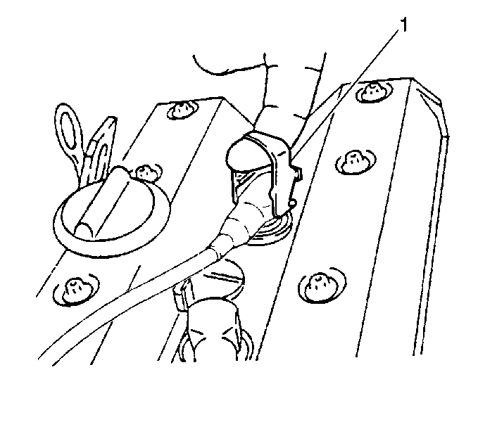
- Rotate the orange tool (1) from the storage position, and remove the spark plug boots from spark plugs.
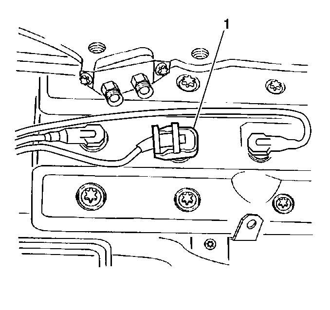
- Use the spark plug boot remover tool (1) attached to spark plug boot.
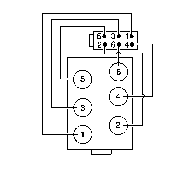
- Remove the spark plug wire harness from routing retainers on valve covers and from ignition coil.
Caution: Unless directed otherwise, the ignition and start switch must be in the OFF or LOCK position, and all electrical loads must be OFF before servicing any electrical component. Disconnect the negative battery cable to prevent an electrical spark should a tool or equipment come in contact with an exposed electrical terminal. Failure to follow these precautions may result in personal injury and/or damage to the vehicle or its components.
Notice: Pull on the spark plug boot, the heat shield or use an approved spark plug boot removal tool, twisting a half-turn to release the seal while removing. Do not pull on the spark plug wire or it may be damaged.


Installation Procedure
- Install the spark plug wires to ignition coil.
- Install the spark plug wires to routing retainers on valve covers.
- Install the spark plug boots to spark plugs.
- Install spark plug boot remover tool (1) to spark plug boot.
- Position the wiring harness channel.
- Install the wiring harness channel bolts.
- Reposition the A/C compressor hose.
- Install the A/C compressor hose bracket bolt to engine.
Notice: Note the spark plug wire harness routing during harness removal. Improper
routing during installation can cause the following conditions:
• Radio noise • Ignition noise • Spark plug crossfiring • Ground lead shorts • Cutting and chaffing of the wires


Notice: Use the correct fastener in the correct location. Replacement fasteners must be the correct part number for that application. Fasteners requiring replacement or fasteners requiring the use of thread locking compound or sealant are identified in the service procedure. Do not use paints, lubricants, or corrosion inhibitors on fasteners or fastener joint surfaces unless specified. These coatings affect fastener torque and joint clamping force and may damage the fastener. Use the correct tightening sequence and specifications when installing fasteners in order to avoid damage to parts and systems.
Tighten
Tighten the wiring harness channel bolts to 8 N·m (71 lb in).
Tighten
Tighten the compressor hose bracket bolt to 8 N·m (71 lb in).
