Tools Required
| • | J 42069 Timing Belt Alignment Kit |
| • | J 42098 Crank Hub TORX® Socket |
Timing Belt Adjustment Checking
Important: The following steps are the continuation of the Timing Belt Replacement and must not be performed as a stand-alone operation.
It is not uncommon to repeat steps and make several engine revolutions to achieve the proper level of timing belt adjustment.- Apply the J 42069-20 to camshaft gears 1 and 2.
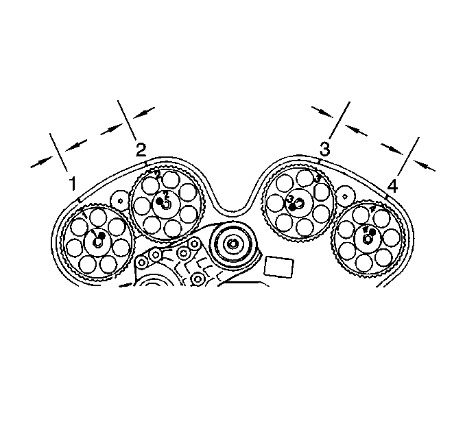
- Inspect the relationship of the marks on the camshaft gears to the marks on the J 42069-20. They must match exactly, if not, timing belt adjustment is required.
- Continue to the next applicable procedure:
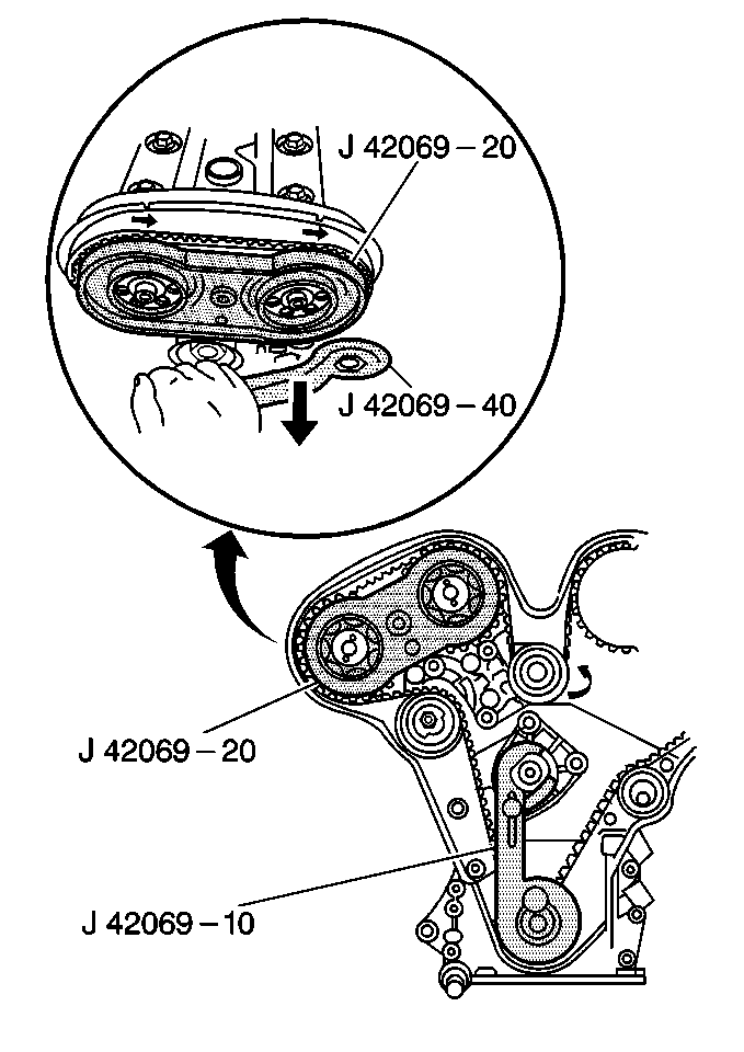
Marks on Camshaft Gears 1 and 2 Align to the LEFT of J 42069-20
- Loosen the upper idler pulley bolt.
- Use the J 42069-40 to turn the eccentric on the upper idler pulley COUNTERCLOCKWISE until the marks on the camshaft gears and on the J 42069-20 are in alignment, the high point of the idler pulley eccentric will be in approximately the 9 o'clock position.
- Remove the J 42069-10 and the J 42069-20.
- Rotate the crankshaft in the engine rotational direction, clockwise 2 revolutions using the J 42098 until reaching 60 degrees Before Top Dead Center (BTDC).
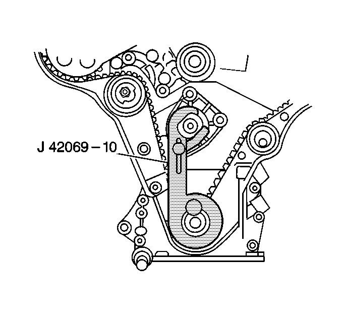
- Install the J 42069-10 to the crankshaft sprocket with the knurled bolt.
- Rotate the crankshaft in the engine rotational direction, clockwise using the J 42098 until the lever of the J 42069-10 firmly contacts the water pump pulley flange.
- Secure the moveable lever of the tool to the water pump pulley flange.
- Install the J 42069-20 to camshaft gears 1 and 2.
- Inspect the alignment of the marks on the camshaft gears in reference to the marks on the J 42069-20.
- Repeat the procedure again if the marks do not align.
- If camshaft gears 1 and 2 are properly aligned, set the final timing belt tensioner as outlined in Timing Belt Tensioner Adjustment at the end of this procedure.
Notice: Refer to Fastener Notice in the Preface section.

Tighten
Tighten the upper idler pulley bolt, while holding the eccentric in place with the J 42069-40 to prevent movement, to 40 N·m (30 lb ft).
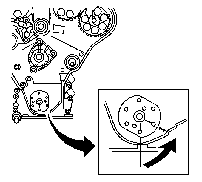
The 60 degrees BTDC point can be identified by the index mark on the oil pump cover.

Important: Ensure the moveable lever is positioned toward the crankshaft.
The #1 cylinder is at Top Dead Center (TDC) at this point.
Important: Ensure that the crankshaft is not 180 degrees off TDC.
The reference marks on the camshaft gears should be aligned with the corresponding notches on the rear timing belt cover at this point. If they are not aligned, the engine is 180 degrees off.Marks on Camshaft Gears 1 and 2 Align to the RIGHT of J 42069-20
- Loosen the upper idler pulley bolt.
- Slacken the timing belt by turning the eccentric on the upper idler pulley CLOCKWISE with the J 42069-40 until the marks on the camshaft gears and the marks on the J 42069-20 are in alignment, the high point of the idler pulley eccentric will be in approximately the 9 o'clock position.
- Remove the J 42069-10 and the J 42069-20.
- Rotate the crankshaft in the engine rotational direction, clockwise 2 revolutions using the J 42098 until reaching 60 degrees Before Top Dead Center (BTDC).
- Install the J 42069-10 to the crankshaft sprocket with the knurled bolt.
- Rotate the crankshaft in the engine rotational direction, clockwise using the J 42098 until the lever of the J 42069-10 firmly contacts the water pump pulley flange.
- Secure the moveable lever of the tool to the water pump pulley flange.
- Install the J 42069-20 to camshaft gears 1 and 2.
- Inspect the alignment of the marks on the camshaft gears in reference to the marks on the J 42069-20.
- Repeat the procedure again if the marks do not align.
- If camshaft gears 1 and 2 are properly aligned, set the final timing belt tensioner as outlined in Timing Belt Tensioner Adjustment at the end of this procedure.
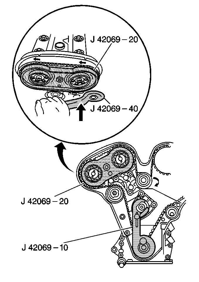
Tighten
Tighten the upper idler pulley bolt, while holding the eccentric in place with the J 42069-40 to prevent movement, to 40 N·m (30 lb ft).

The 60 degrees BTDC point can be identified by the index mark on the oil pump cover.

Important: Ensure the moveable lever is positioned toward the crankshaft.
The #1 cylinder is at Top Dead Center (TDC) at this point.
Important: Ensure that the crankshaft is not 180 degrees off TDC.
The reference marks on the camshaft gears should be aligned with the corresponding notches on the rear timing belt cover at this point. If they are not aligned, the engine is 180 degrees off.Timing Belt Tensioner Adjustment
Important: The following steps are the COMPLETION of adjusting the timing belt and must not be performed as a stand alone operation.
- With the J 42069-10 in place locking the crankshaft at TDC:
- If the timing belt upper idler pulley bolt has not been previously torqued to specification:
- Remove the J 42069-10 and the J 42069-20.
- For final inspection, once again rotate the crankshaft in the engine rotational direction, clockwise 2 revolutions using the J 42098 until reaching 60 degrees BTDC.
- Install the J 42069-10 to the crankshaft sprocket.
- Rotate the crankshaft in the engine rotational direction, clockwise using the J 42098 until the lever of the J 42069-10 firmly contacts the water pump pulley flange.
- Secure the moveable lever of the tool to the water pump pulley flange.
- Inspect the alignment of the reference marks on the camshaft gears with the notches on the rear timing belt cover, as well as the mark on the crankshaft sprocket and oil pump housing.
- Use the J 42069-20 to inspect the alignment of the camshaft gears 3 and 4.
- Use the J 42069-20 to inspect the alignment of the camshaft gears 1 and 2.
- Repeat the procedure again if the marks do not align exactly.
- If the reference marks match exactly, further timing belt adjustment IS NOT necessary.
- Remove the J 42069-10 and the J 42069-20.
- Install the crankshaft balancer. Refer to Crankshaft Balancer Replacement .
- Install the timing belt cover. Refer to Timing Belt Cover Replacement .
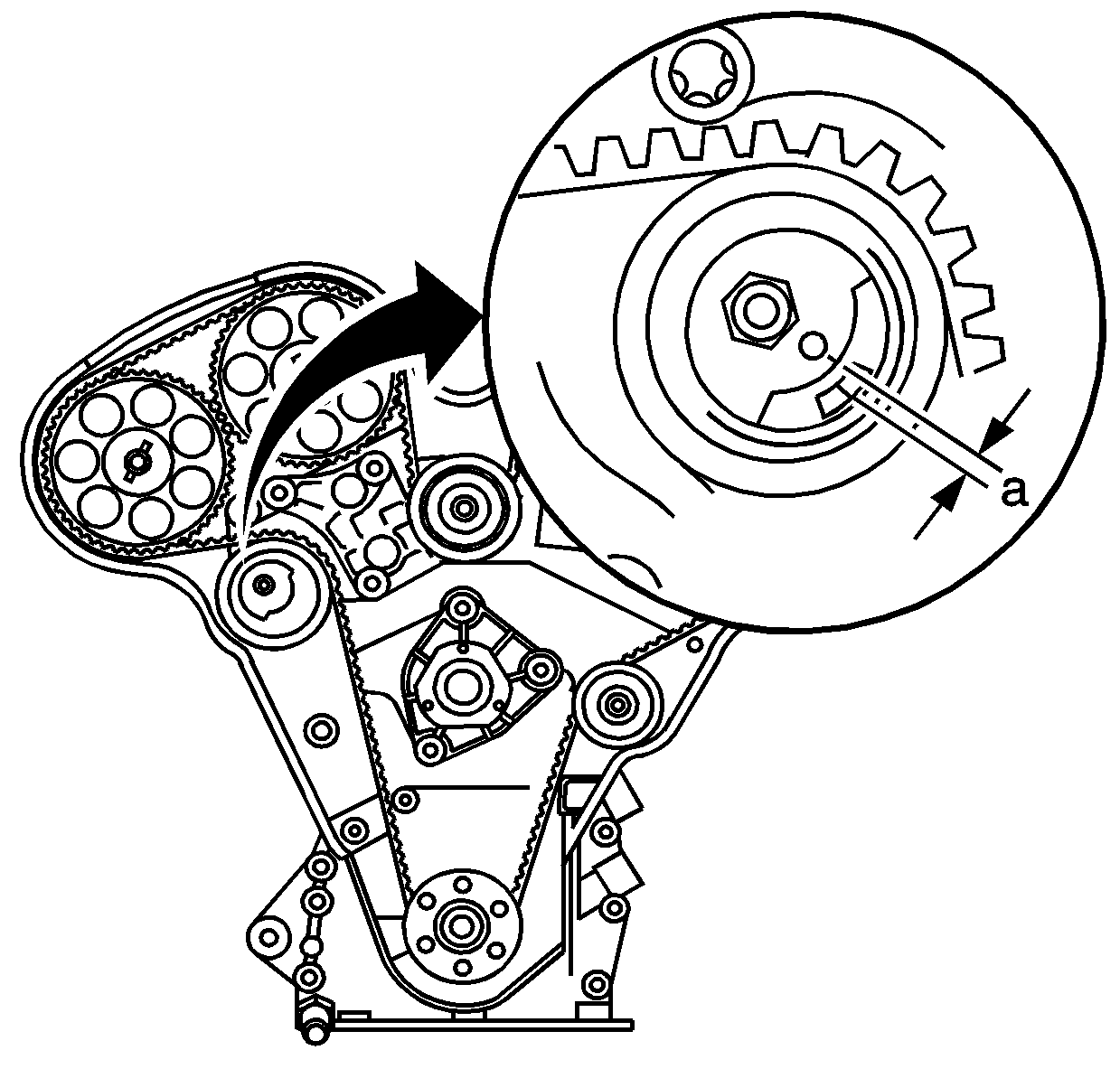
| 1.1. | Loosen the timing belt eccentric locking nut. |
| 1.2. | Turn the eccentric counter clockwise to full stop, then back to the following specification: |
| • | NEW BELT |
| • | until the reference mark is 3-4 mm (0.118-0.157 in) (a) above the datum line. |
| • | USED BELT |
| • | until the reference mark is aligned with the datum line. |
Tighten
Tighten the timing belt tensioner eccentric locking nut to 20 N·m (15 lb ft).

Tighten
Tighten the timing belt upper idler pulley bolt while holding the eccentric in place with the J 42069-40 to prevent movement, to 40 N·m (30 lb ft).

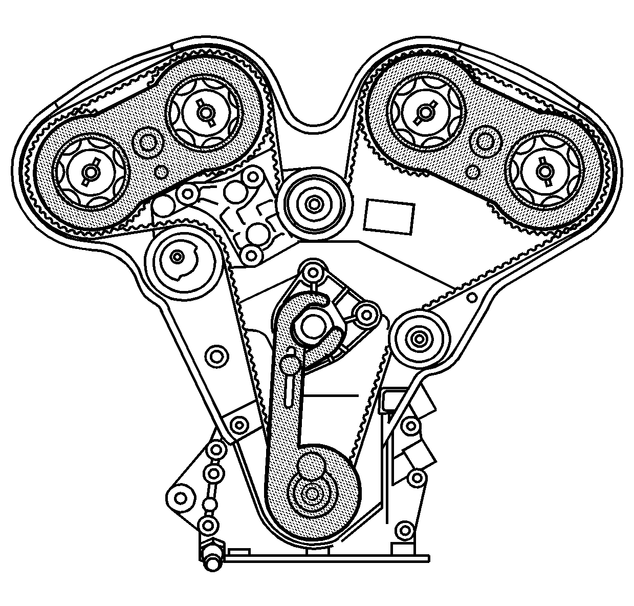
Important: The alignment marks on the timing belt will no longer align with the marks on the camshaft gears after one or more engine revolutions.
Continue with reassembly of the engine.
