For 1990-2009 cars only
Tools Required
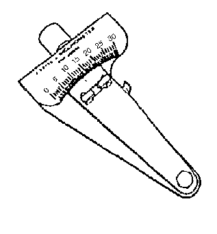
J 23498-A Driveshaft Inclinometer
The working angle of a U-joint is formed by the difference between the angles of two shafts that intersect.
| • | No working angle should not be equal to zero. An angle of 0 degrees will cause premature U-joint wear due to a lack of rotation of the needle bearings in the U-joint. |
| • | Always orientate the J 23498-A so that it faces the same side of the vehicle for each measurement taken. |
| • | Be sure to accurately record the measurements taken. |
Measurement Procedure
- Raise and suitably support the vehicle; ensure that the rear wheels are free to rotate. Suspension travel will not affect the driveline angles on this vehicle. Refer to Lifting and Jacking the Vehicle in General Information.
- Place the transmission in NEUTRAL.
- Clean any corrosion or foreign material from the U-joint bearing caps.
- Rotate the propeller shafts to align the rear propeller shaft yoke flanges vertically.
- Install the J 23498-A to the lower U-joint bearing cap of the rear propeller shaft yoke.
- Measure and record the angle of the rear propeller shaft on the J 23498-A .
- Rotate the propeller shafts to align the front propeller shaft yoke flanges vertically.
- Install the J 23498-A to the lower U-joint bearing cap of the front propeller shaft yoke.
- Measure and record the angle of the front propeller shaft on the J 23498-A .
- Calculate the working angle at the intersection of the two shafts.
- Compare the calculated working angle to the working angle specification.
- If the calculated working angle exceeds the specification, then the angle requires adjustment.
- If the calculated working angle is 1/2 degree or less, then the angle requires adjustment.
Subtract the larger number from the smaller to obtain the working angle.
Specification
Maximum U-joint working angle: 0.75 degrees
