Brake Pressure Modulator Valve Replacement CTS
Caution: Refer to Brake Dust Caution in the Preface section.
Removal Procedure
Caution: For safety reasons, the brake pressure modulator valve assembly must not be repaired, the complete unit must be replaced. With the exception of the EBCM, no screws on the brake pressure modulator valve assembly may be loosened. If screws are loosened, it will not be possible to get the brake circuits leak-tight and personal injury may result.
- Turn OFF the ignition.
- Thoroughly clean all contaminants from around the EBCM.
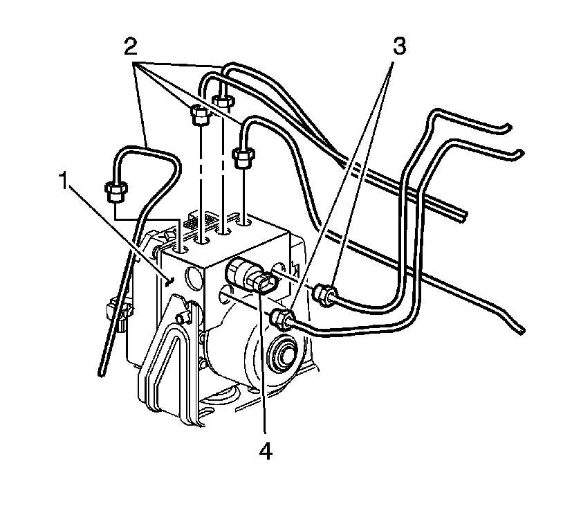
- Remove the 2 master cylinder brake pipes (3) from the BPMV (1).
- Remove the 4 wheel brake pipes (2) from the BPMV (1).
- Clean any brake fluid spillage from the BPMV (1).
- If equipped with a brake fluid pressure sensor (4), disconnect the electrical connector, from the brake fluid pressure sensor.
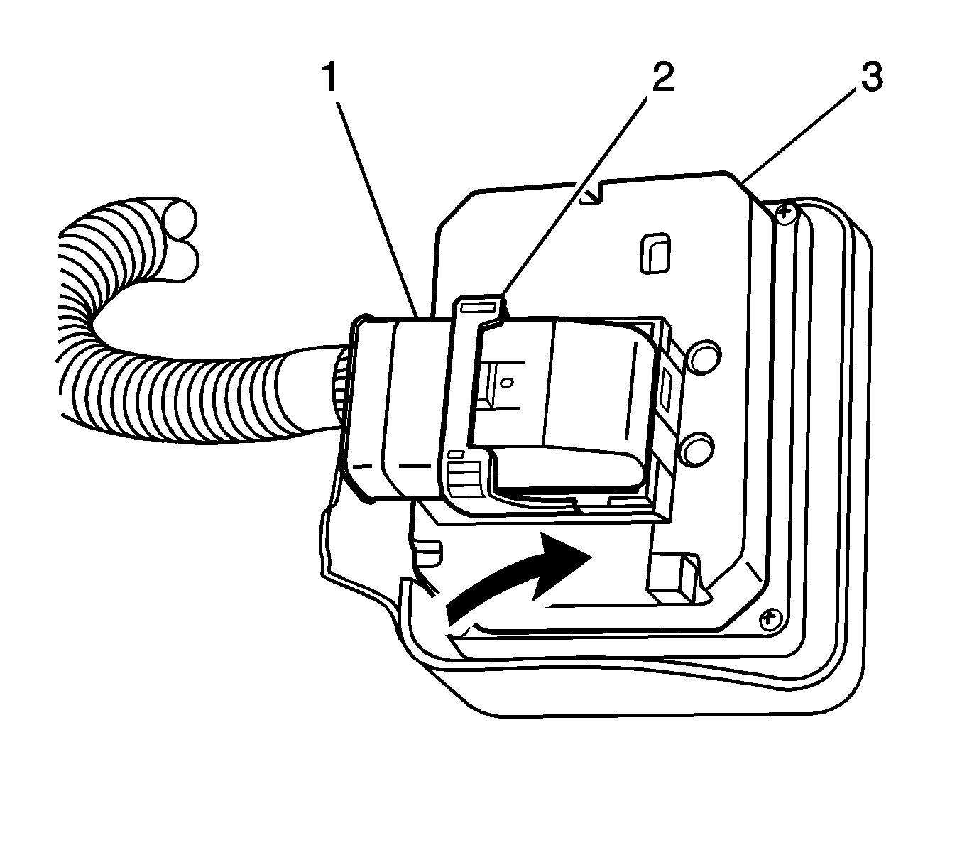
- Rotate the EBCM connector tab (2) up to the unlocked position.
- Disconnect the EBCM electrical connector (1) from the EBCM (3) and position out of the way.
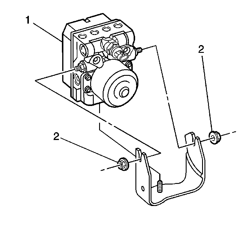
- Remove the 2 BPMV bracket nuts (2).
- Remove the EBCM/BPMV assembly (1) from the BPMV bracket.
- Remove the 4 EBCM to BPMV screws.
- Clean the surface of the EBCM/BPMV assembly.
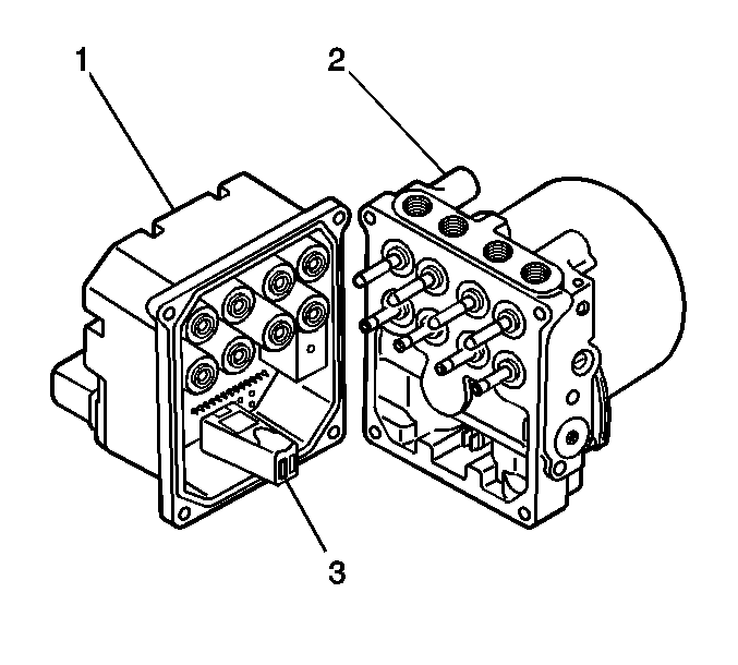
- Remove the EBCM (1) from the BPMV (2).
Important: The area around the electronic brake control module (EBCM) must be free from loose dirt to prevent contamination of disassembled ABS components.
Notice: Refer to Brake Fluid Effects on Paint and Electrical Components Notice in the Preface section.
Caution: Brake fluid may irritate eyes and skin. In case of contact, take the
following actions:
• Eye contact--rinse thoroughly with water. • Skin contact--wash with soap and water. • If ingested--consult a physician immediately.
Important: Record the location of all brake pipes to the brake pressure modulator valve (BPMV) for use as an aid during installation.
Notice: To prevent equipment damage, never connect or disconnect the wiring harness connection from the EBCM with the ignition switch in the ON position.
Installation Procedure
- Clean the seal surface of the BPMV.
- Install the EBCM (1) to the BPMV (2).
- Make sure that the internal pump motor connector (3) is installed into the new EBCM (1) prior to EBCM replacement.
- Install the 4 EBCM to BPMV screws.
- Install the EBCM/BPMV assembly (1) to the BPMV bracket.
- Install the 2 BPMV bracket nuts (2).
- Connect the EBCM electrical connector (1) to the EBCM (3).
- Rotate the EBCM connector tab (2) to the locked position.
- Install the 4 wheel brake pipes (2) to the BPMV (1) using the locations recorded during the removal procedure.
- Install the 2 master cylinder brake pipes (3) to the BPMV (1) using the locations recorded during the removal procedure.
- If equipped with a brake fluid pressure sensor (4), connect the electrical connector.
- Fill and bleed the hydraulic brake system. Refer to Master Cylinder Reservoir Filling and Hydraulic Brake System Bleeding .
- Perform the System Check-Vehicle. Refer to Diagnostic System Check - Vehicle .

Notice: Refer to Fastener Notice in the Preface section.
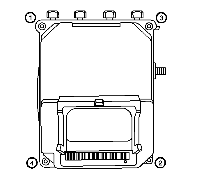
Tighten
Tighten the EBCM to BPMV screws in sequence (1-4) to 5 N·m (44 lb in).
Important: Make sure that the rubber isolator is installed on the BPMV. The isolator protects the EBCM/BPMV assembly from vehicle vibrations.

Tighten
Tighten the BPMV nuts to 10 N·m (89 lb in).

Notice: To prevent equipment damage, never connect or disconnect the wiring harness connection from the EBCM with the ignition switch in the ON position.
Caution: The brake pipes must be fully installed to the brake pipe mounting retainers on the frame. Failure to properly retain the brake pipes may cause the pipes to contact the frame and/or the transmission resulting in possible loss of brake fluid and personal injury.

Caution: Make sure brake pipes are correctly connected to BPMV. If brake pipes are switched by mistake Inlet vs. Outlet, wheel lockup will occur and personal injury may result.
Important: If a new BPMV is being installed, remove the shipping plugs from the valve openings.
Tighten
Tighten the wheel brake pipes to 27 N·m (20 lb ft).
Tighten
Tighten the master cylinder brake pipes to 27 N·m (20 lb ft).
Brake Pressure Modulator Valve Replacement CTS-V
Caution: Refer to Brake Dust Caution in the Preface section.
Removal Procedure
Caution: For safety reasons, the brake pressure modulator valve assembly must not be repaired, the complete unit must be replaced. With the exception of the EBCM, no screws on the brake pressure modulator valve assembly may be loosened. If screws are loosened, it will not be possible to get the brake circuits leak-tight and personal injury may result.
- Turn OFF the ignition.
- Remove the right front tire and wheel assembly. Refer to Tire and Wheel Removal and Installation in Tires and Wheels.
- Remove the front air deflector. Refer to Front Air Deflector Replacement in Body Front End.
- Remove the right front wheel house liner. Refer to Front Wheelhouse Liner Replacement in Body Front End.
- Thoroughly clean all contaminants from around the EBCM.
- Remove the upper radiator support bracket. Refer to Radiator Support Bracket Replacement in Engine Cooling.
- Carefully lift the right side of the radiator up and move forward to access the front brake pipe of the brake pressure modulator valve (BPMV).
- Carefully remove the brake pressure switch electrical connector and position out of the way.
- Remove the 2 master cylinder brake pipes (3) from the BPMV (1).
- Carefully remove the front wheel brake pipe from the BPMV.
- Carefully move the right side of the radiator froward into the insulator in the frame.
- Remove the remaining wheel brake pipes (2) from the BPMV (1).
- Clean any brake fluid spillage from the BPMV (1).
- If equipped with a brake fluid pressure sensor (4), disconnect the electrical connector, from the brake fluid pressure sensor.
- Raise and support the vehicle. Refer to Lifting and Jacking the Vehicle in General Information.
- Remove the front air deflector. Refer to Front Air Deflector Replacement in Body Front End.
- Rotate the EBCM connector tab (2) up to the unlocked position.
- Disconnect the EBCM electrical connector (1) from the EBCM (3) and position out of the way.
- Remove the 6 BPMV mounting bolts from under the mounting bracket.
- Remove the EBCM/BPMV assembly from the BPMV bracket.
- Remove and discard the 4 EBCM to BPMV screws.
- Clean the surface of the EBCM/BPMV assembly.
- Remove the EBCM (1) from the BPMV (2).
Important: The area around the electronic brake control module (EBCM) must be free from loose dirt to prevent contamination of disassembled ABS components.
Notice: Refer to Brake Fluid Effects on Paint and Electrical Components Notice in the Preface section.
Caution: Brake fluid may irritate eyes and skin. In case of contact, take the
following actions:
• Eye contact--rinse thoroughly with water. • Skin contact--wash with soap and water. • If ingested--consult a physician immediately.

Important: Record the location of all brake pipes to the BPMV for use as an aid during installation.

Notice: To prevent equipment damage, never connect or disconnect the wiring harness connection from the EBCM with the ignition switch in the ON position.

Installation Procedure
- Clean the seal surface of the BPMV.
- Install the EBCM (1) to the BPMV (2).
- Make sure that the internal pump motor connector (3) is installed into the new EBCM (1) prior to EBCM replacement.
- Install the 4 NEW EBCM to BPMV screws.
- Install the EBCM/BPMV assembly to the BPMV bracket.
- Install the 6 BPMV mounting bolts.
- Connect the EBCM electrical connector (1) to the EBCM (3).
- Rotate the EBCM connector tab (2) to the locked position.
- Install the front air deflector. Refer to Front Air Deflector Replacement in Body Front End.
- Lower the vehicle.
- Install the 3 wheel brake pipes (2) to the BPMV (1) using the locations recorded during the removal procedure.
- Carefully lift the right side of the radiator up and move rearward to access the front brake pipe of the BPMV.
- Carefully install the front brake pipe from the BPMV.
- Install the 2 master cylinder brake pipes (3) to the BPMV (1) using the locations recorded during the removal procedure.
- Carefully connect the brake pressure switch electrical connector.
- Carefully move the right side of the radiator rearward into the insulator in the frame.
- Install the upper radiator support bracket. Refer to Radiator Support Bracket Replacement in Engine Cooling.
- If equipped with a brake fluid pressure sensor (4), connect the electrical connector.
- Install the right front wheel house liner. Refer to Front Wheelhouse Liner Replacement in Body Front End.
- Install the air deflector. Refer to Front Air Deflector Replacement in Body Front End.
- Install the right front tire and wheel assembly. Refer to Tire and Wheel Removal and Installation in Tires and Wheels.
- Fill and bleed the hydraulic brake system. Refer to Master Cylinder Reservoir Filling and Hydraulic Brake System Bleeding in Hydraulic Brakes.
- Perform the Auto Bleed Procedure. Refer to Antilock Brake System Automated Bleed Procedure .
- Perform the System Check-Vehicle. Refer to Diagnostic System Check - Vehicle in Vehicle DTC Information.

Notice: Refer to Fastener Notice in the Preface section.

Important: Use New EBCM/BPMV screws after separating the EBCM from the BPMV.
Tighten
Tighten the (4) NEW EBCM to BPMV screws in
sequence (1-4) to 5 N·m (44 lb in).
Tighten
Tighten the BPMV nuts to 10 N·m (89 lb in).

Notice: To prevent equipment damage, never connect or disconnect the wiring harness connection from the EBCM with the ignition switch in the ON position.
Caution: The brake pipes must be fully installed to the brake pipe mounting retainers on the frame. Failure to properly retain the brake pipes may cause the pipes to contact the frame and/or the transmission resulting in possible loss of brake fluid and personal injury.

Caution: Make sure brake pipes are correctly connected to BPMV. If brake pipes are switched by mistake Inlet vs. Outlet, wheel lockup will occur and personal injury may result.
Important: If a new BPMV is being installed, remove the shipping plugs from the valve openings.
Tighten
Tighten the back 3 wheel brake pipes
to 27 N·m (20 lb ft).
Tighten
Tighten the wheel brake pipe to 27 N·m
(20 lb ft).
Tighten
Tighten the master cylinder brake pipes to 27 N·m
(20 lb ft).
