For 1990-2009 cars only
Removal Procedure
- Remove the left bank secondary timing chain. Refer to Secondary Camshaft Drive Chain Replacement - Left Side .
- Remove the oil level indicator. Refer to Oil Level Indicator and Tube Replacement .
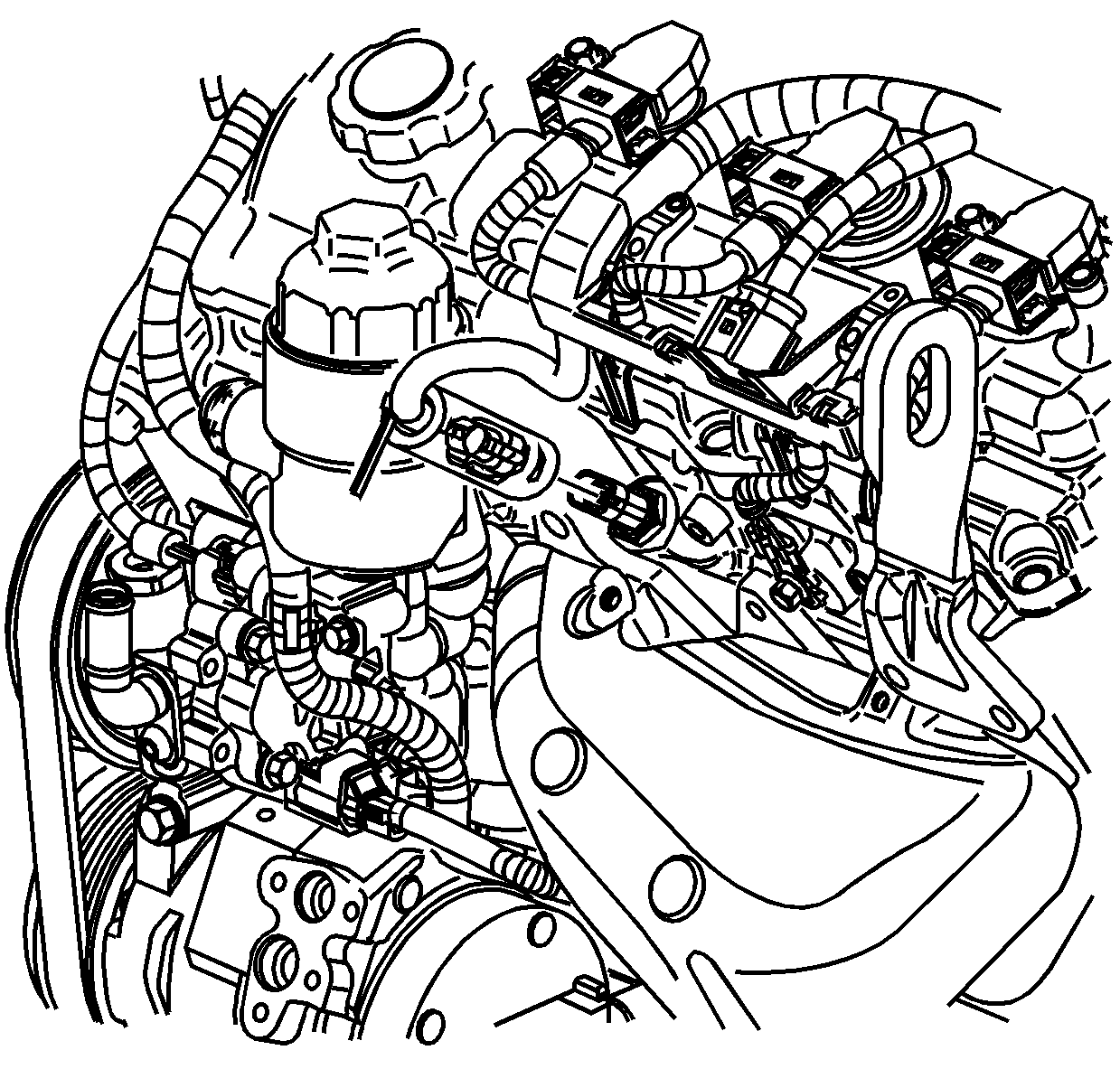
- Remove the heat shield from the coolant temperature sensor and disconnect the coolant temperature sensor electrical connector.
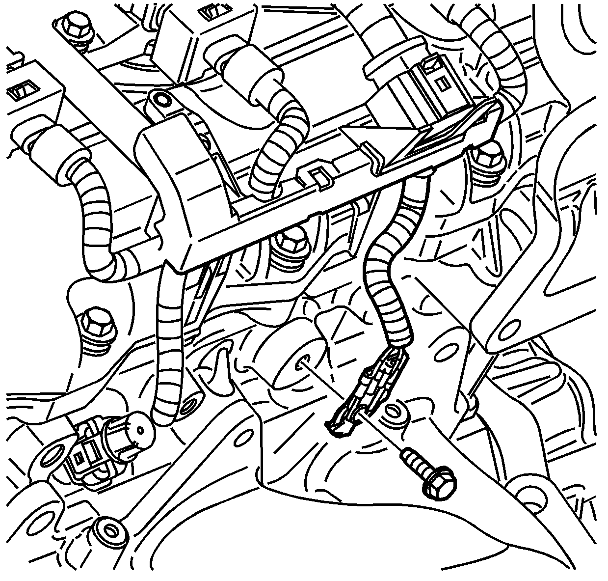
- Remove the wiring harness ground from the cylinder head.
- Disconnect the wiring harness electrical connector located at the side of the cylinder head.
- Remove the wiring harness connector bracket from the side of the cylinder head.
- Remove the power steering pump bolts. Refer to Power Steering Pump Removal .
- Remove the surge tank hose from the bracket at the rear of the cylinder head.
- Remove the wiring harness bracket from the rear of the cylinder head.
- Remove the catalytic converter. Refer to Catalytic Converter Replacement - Left Side .
- Remove the oil level indicator tube. Refer to Oil Level Indicator and Tube Replacement .
- Remove the oil filter adapter upper bolt.
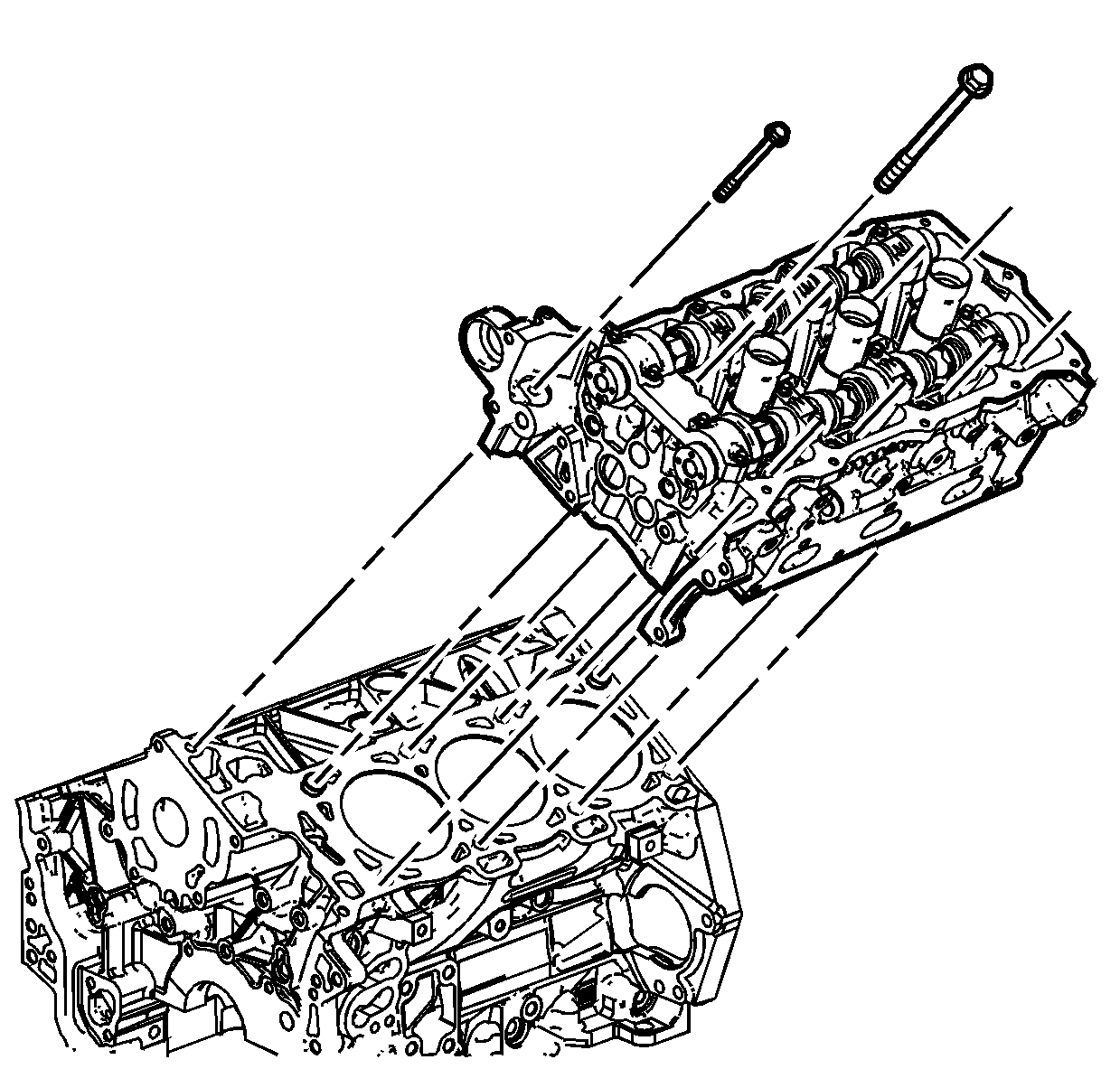
- Remove the cylinder head with the exhaust manifold. Refer to Cylinder Head Removal - Right Side .
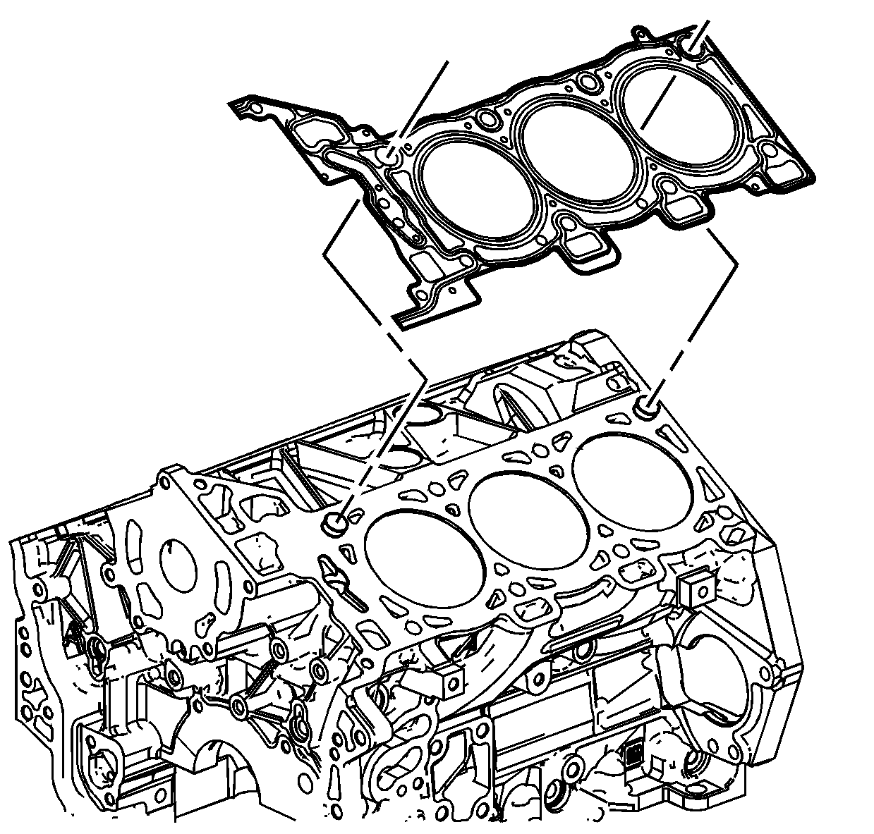
- Remove and discard the cylinder head gasket.
- Clean and inspect the cylinder head and the engine block sealing surfaces. Refer to Cylinder Head Cleaning and Inspection and Engine Block Cleaning and Inspection .
- If necessary, perform the following steps:


Important: DO NOT disconnect the power steering pipes and/or hoses.
Important: Do not remove the oil filter adapter.


| • | Remove the exhaust manifold from the cylinder head. Refer to Exhaust Manifold Removal - Left Side . |
| • | Disassemble the cylinder head. Refer to Cylinder Head Disassemble . |
Installation Procedure
- If necessary, perform the following steps:
- Install a NEW cylinder head gasket.
- Carefully, install the cylinder head with the exhaust manifold to the engine. Refer to Camshaft Installation - Left Side .
- Install the oil filter adapter upper bolt. Refer to Oil Filter Adapter Installation .
- Install the oil level indicator tube. Refer to Oil Level Indicator and Tube Replacement .
- Install the catalytic converter to the exhaust manifold. Refer to Catalytic Converter Replacement - Left Side .
- Install the wiring harness bracket to the rear of the cylinder head.
- Install the surge tank hose to the bracket at the rear of the cylinder head.
- Install the power steering pump bolts. Refer to Power Steering Pump Installation .
- Install the wiring harness connector bracket from the side of the cylinder head.
- Disconnect the wiring harness electrical connector located at the side of the cylinder head.
- Install the wiring harness ground to the cylinder head.
- Install the coolant temperature sensor electrical connector heat shield.
- Install the oil level indicator. Refer to Oil Level Indicator and Tube Replacement .
- Install the left bank secondary timing chain. Refer to Secondary Camshaft Drive Chain Replacement - Left Side .
| • | Assemble the cylinder head. Refer to Cylinder Head Assemble . |
| • | Install the exhaust manifold to the cylinder head. Refer to Exhaust Manifold Installation - Left Side . |


Notice: Refer to Fastener Notice in the Preface section.

Tighten
Tighten the wiring harness ground bolt to 10 N·m (89 lb in).

