For 1990-2009 cars only
Removal Procedure
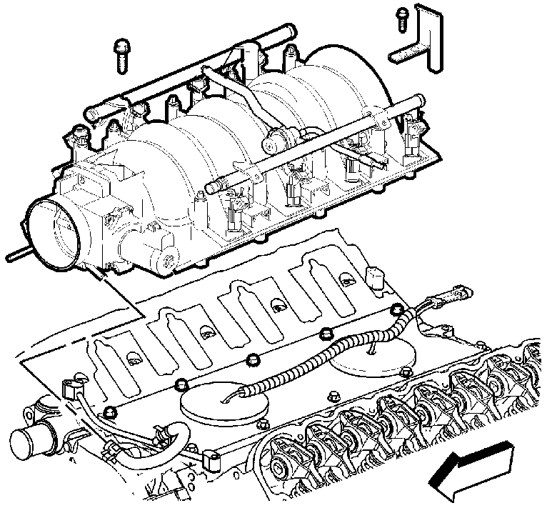
Important: The intake manifold, throttle body, fuel injection rail, and injectors may be removed as an assembly. If not servicing the individual components, remove the manifold as a complete assembly.
- Drain the cooling system. Refer to Cooling System Draining and Filling in Engine Cooling.
- Relieve the fuel system pressure. Refer to Fuel Pressure Relief in Engine Controls - 5.7L.
- If replacing the intake manifold, perform the following:
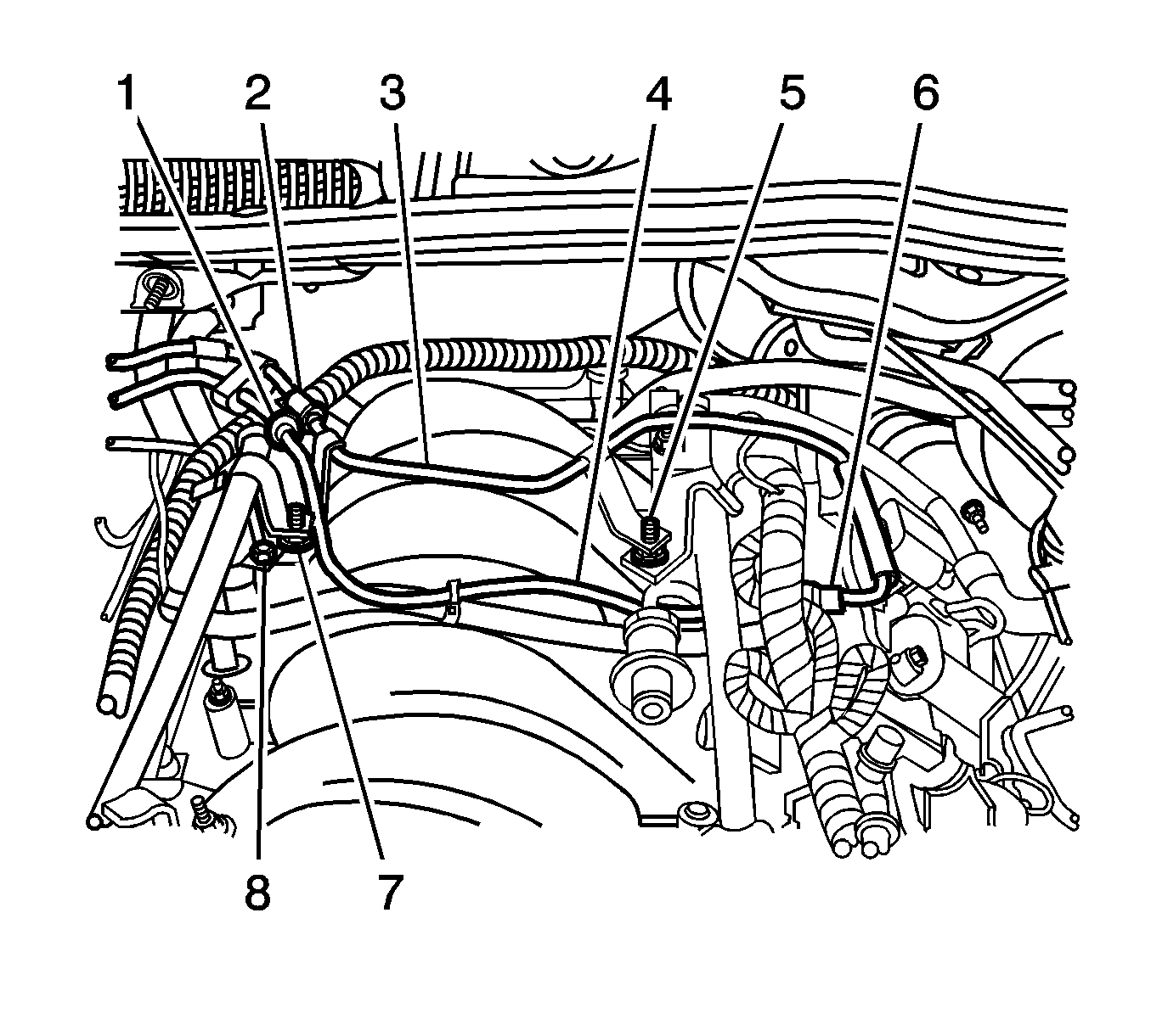
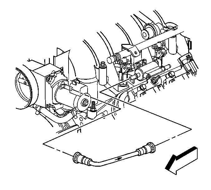
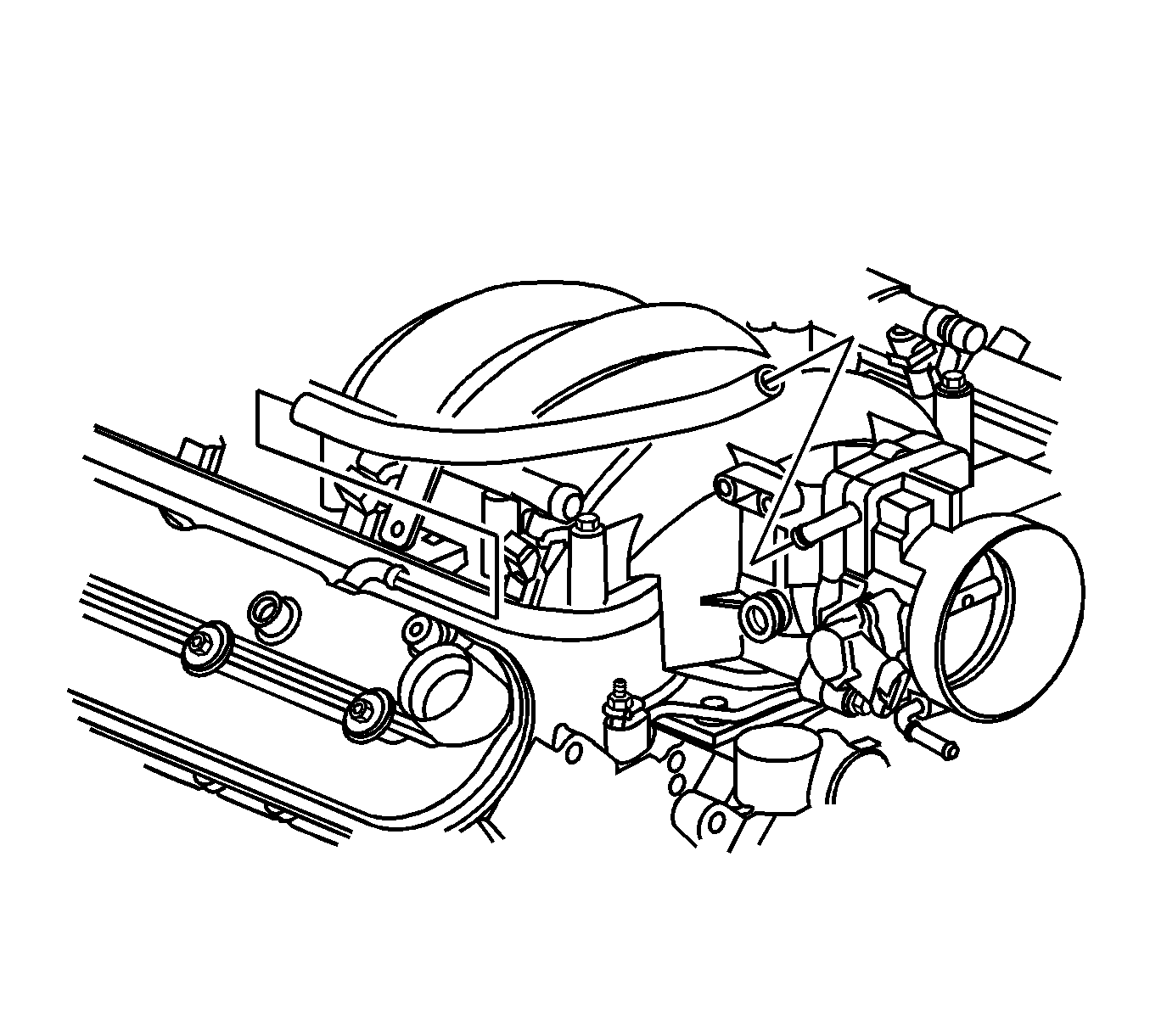
- Disconnect the fuel feed hose (2). Refer to Fuel Hose/Pipes Replacement - Engine Compartment in Engine Controls - 5.7L.
- Disconnect the evaporative emission (EVAP) canister purge tube from the intake manifold.
- Disconnect the EVAP canister purge tube from the EVAP canister purge solenoid valve.
- Remove the EVAP canister purge tube.
- Disconnect the EVAP canister purge tube (4) from the EVAP canister purge solenoid valve.
- Disconnect the EVAP canister purge tube from the fuel feed pipe.
- Disconnect the EVAP canister purge tube from the rear of the right cylinder head (1).
- Remove the EVAP canister purge tube from under the fuel rail and remove the tube from the vehicle.
- Disconnect the throttle position (TP) sensor electrical connector.
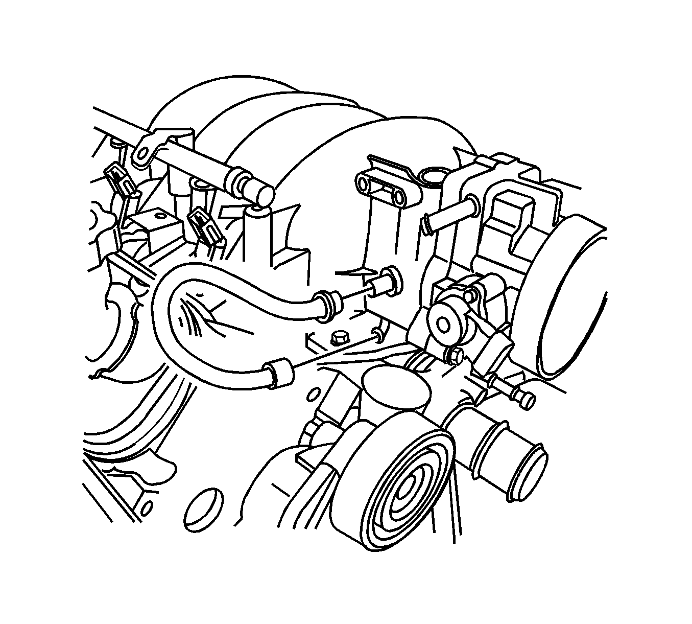
- Remove the coolant air bleed hose. Refer to Engine Coolant Air Bleed Hose Replacement in Engine Cooling.
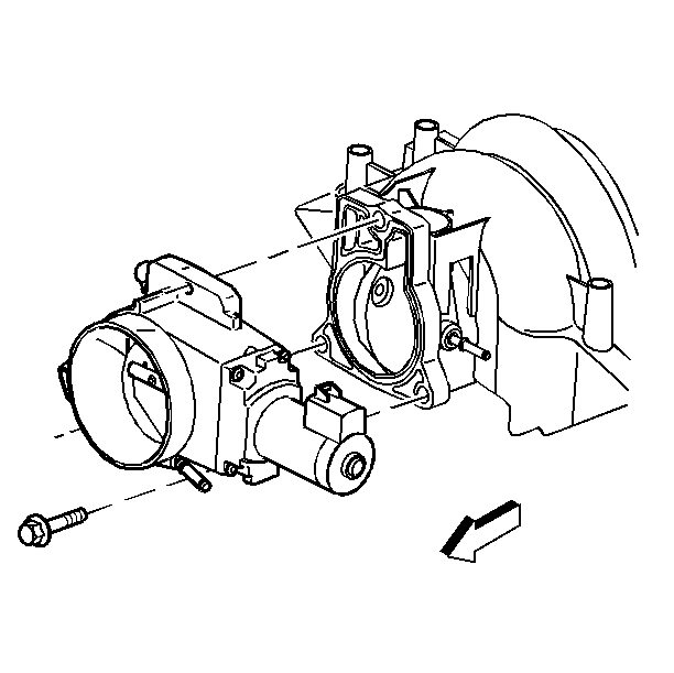
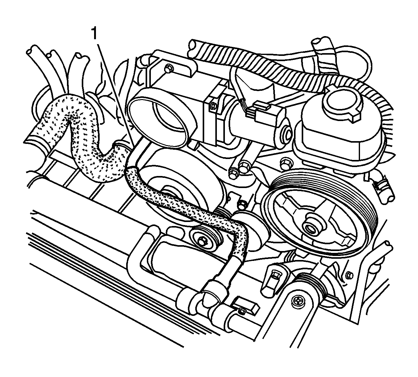
- Disconnect the throttle body outlet hose (1) from the throttle body.
- Position the throttle body outlet hose aside.
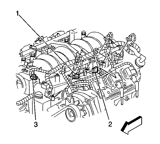
- Disconnect all the fuel injector electrical connectors (1).
- Disconnect the EVAP canister purge solenoid valve electrical connector (2).
- Disconnect the electronic throttle control (ETC) electrical connector (3).
- Remove the EVAP canister purge solenoid valve from the bracket.
- Disconnect the harness clips from the fuel rails.
- Reposition the intake manifold branches of the wiring harness.
- Disconnect the power brake booster vacuum hose at the booster.
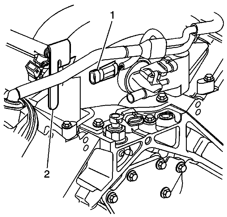
- Remove the knock sensor wire harness (1) clip from the fuel rail stop bracket (2).
- Remove the TP sensor harness clip from the positive crankcase ventilation (PCV) tube.
- Remove the PCV tube from the right rocker arm cover and the throttle body.
- Remove the PCV hose from the valley cover and intake manifold.
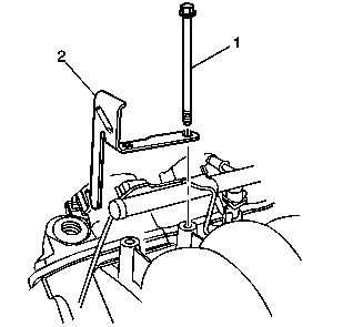
- Remove the intake manifold bolts (1) and fuel rail stop bracket (2).
- Position the intake manifold forward.
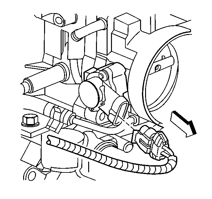
- Disconnect the manifold absolute pressure (MAP) sensor vacuum hose.
- Disconnect the MAP sensor electrical connector.
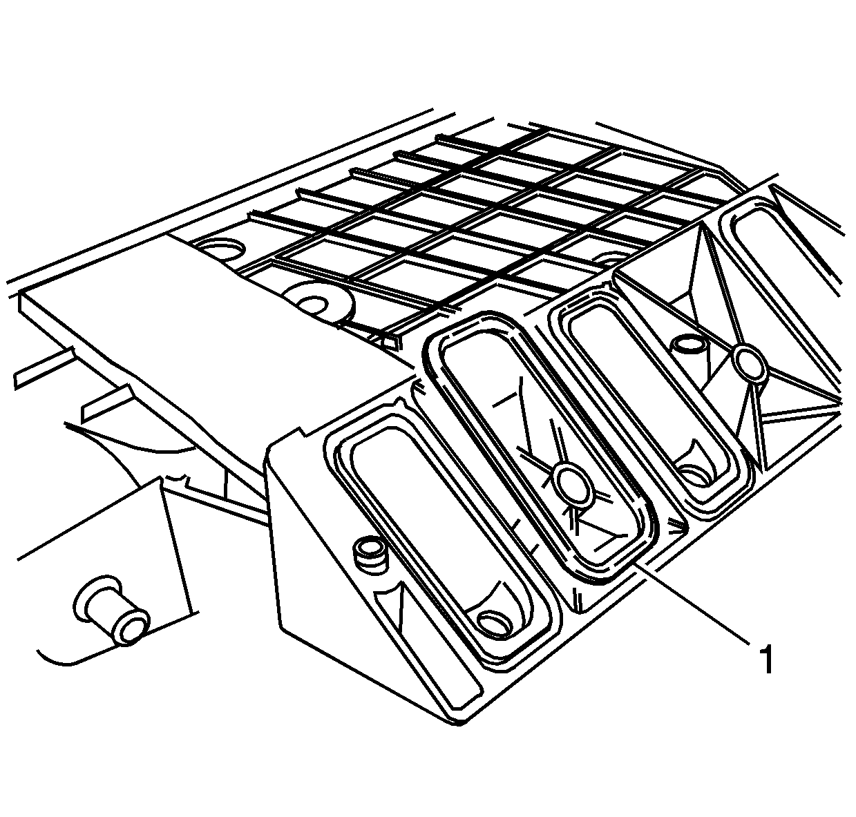
- Remove the intake manifold.
- Remove and discard the intake manifold gaskets (1).
- Clean and inspect the intake manifold. Refer to Intake Manifold Cleaning and Inspection .
| • | Remove the throttle body. Refer to Throttle Body Assembly Replacement in Engine Controls - 5.7L. |
| • | Remove the fuel injectors. Refer to Fuel Injector Replacement in Engine Controls - 5.7L. |

Installation Procedure
Important: DO NOT reuse the intake manifold gaskets. Install NEW intake manifold gaskets.
- Install NEW intake manifold gaskets (1) to the intake manifold.
- Install intake manifold.
- Position the intake manifold forward.
- Connect the MAP sensor vacuum hose.
- Connect the MAP sensor electrical connector.
- Position the intake manifold into place.
- Apply threadlock GM P/N 12345382 (Canadian P/N 10953489), or equivalent to the threads of the intake manifold bolts (1).
- Install the fuel rail stop bracket (2).
- Install the intake manifold bolts (1).
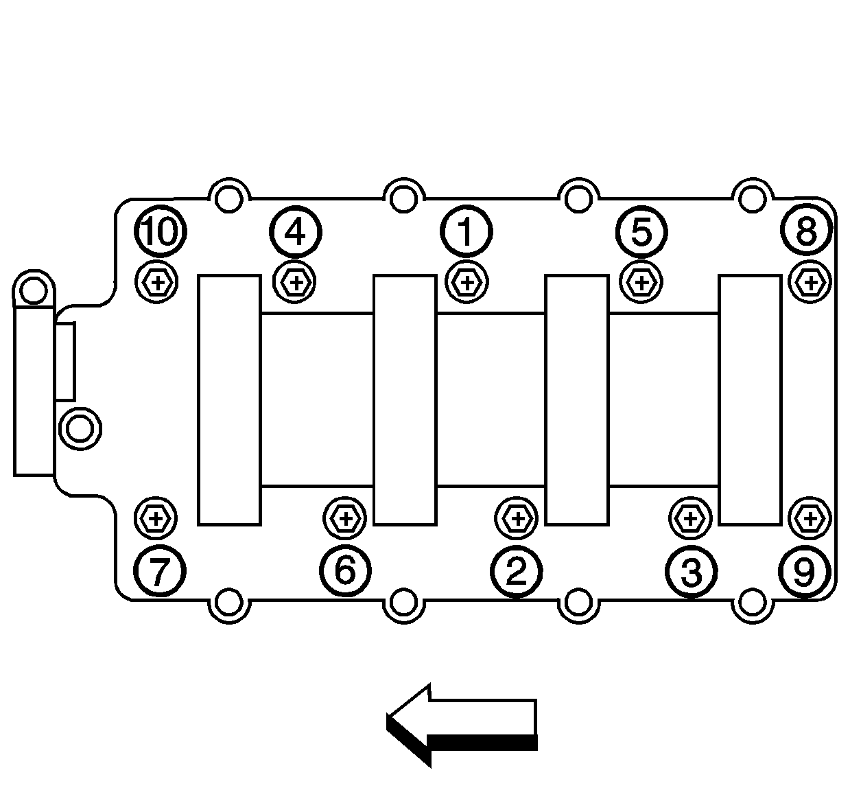
- Tighten the intake manifold bolts.
- Tighten the intake manifold bolts a first pass in sequence to 5 N·m (44 lb in).
- Tighten the intake manifold bolts a second pass in sequence to 10 N·m (89 lb in).
- Install the PCV hose to the valley cover and intake manifold.
- Install the PCV tube to the right rocker arm cover and the throttle body.
- Install the TP sensor harness clip to the PCV tube.
- Install the knock sensor wire harness (1) clip to the fuel rail stop bracket (2).
- Connect the power brake booster vacuum hose to the booster.
- Connect the harness clips to the fuel rails.
- Install the EVAP canister purge solenoid valve to the bracket.
- Connect the ETC electrical connector (3).
- Connect the EVAP canister purge solenoid valve electrical connector (2).
- Connect the fuel injector electrical connectors (1).
- Connect the throttle body outlet hose (1) to the throttle body.
- Install the coolant air bleed hose. Refer to Engine Coolant Air Bleed Hose Replacement in Engine Cooling.
- Connect the TP sensor electrical connector.
- Install the EVAP canister purge tube under the fuel rail.
- Connect the EVAP canister purge tube at the rear of the right cylinder head (1).
- Connect the EVAP canister purge tube to the fuel feed pipe.
- Connect the EVAP canister purge tube (4) to the EVAP canister purge solenoid valve.
- If previously removed, install the fuel injectors. Refer to Fuel Injector Replacement in Engine Controls - 5.7L.
- Connect the fuel feed hose. Refer to Fuel Hose/Pipes Replacement - Engine Compartment in Engine Controls - 5.7L.
- If previously removed, install the throttle body. Refer to Throttle Body Assembly Replacement in Engine Controls - 5.7L.
- Fill the cooling system. Refer to Cooling System Draining and Filling in Engine Cooling.
Caution: Refer to Fuel Rail Stop Bracket Installation Caution in the Preface section.
Notice: Refer to Fastener Notice in the Preface section.
Tighten
