For 1990-2009 cars only
Removal Procedure
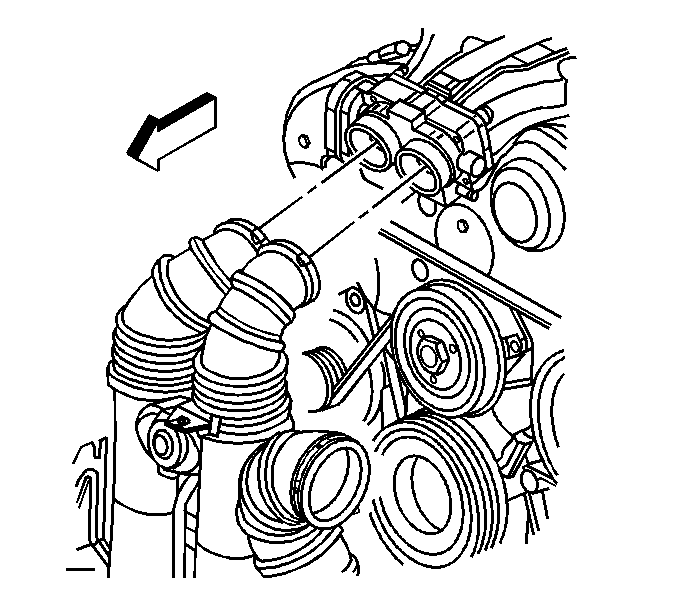
- Remove the intake plenum air inlet hose clamps and hoses from the throttle body.
- Disconnect the fuel pressure regulator atmospheric vent tube from the bottom of the throttle body.
- Remove the bolts securing the throttle body to the intake plenum.
- Remove the throttle body from the intake plenum and crankcase vent adapter, allowing it to be supported by the throttle body inlet heater hose.
- Remove the throttle body O-ring seals.
- Remove the 3 bolts securing the crankcase vent adapter to the intake plenum.
- Lift the crankcase vent adapter from the intake plenum, and position aside.
- Disconnect the vacuum brake booster hose retainer (1) from the rear of the intake plenum-RHD only.
- Disconnect the crankcase ventilation dirty air hose retainer (2) from the fuel pipe.
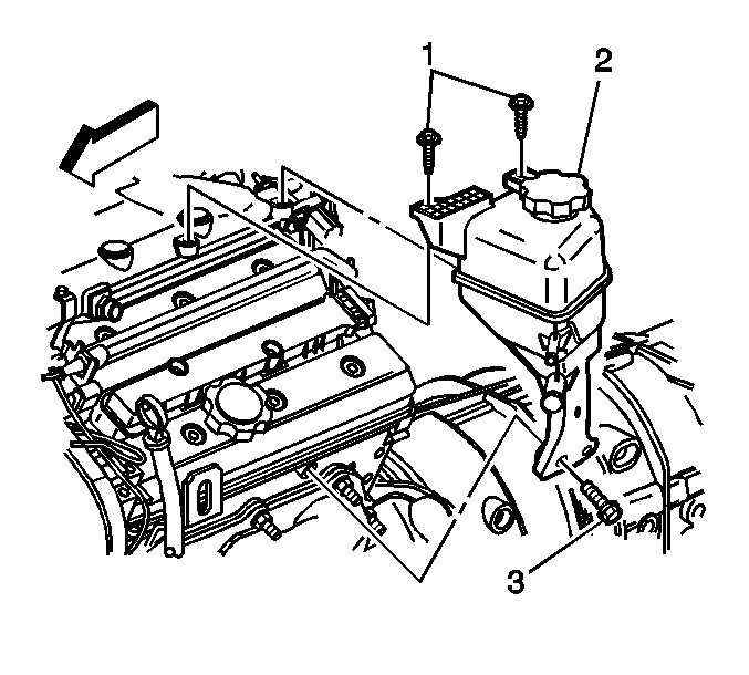
- Remove the remote power steering fluid reservoir mounting bolts (1, 3) ONLY, and position aside.
- Disconnect the electrical connector (1) and vacuum hose (2) from the switchover valve at the rear of the plenum.
- Remove the bolt (1) securing the throttle body heater inlet hose/pipe to the intake plenum (2).
- Disconnect the vacuum brake booster hose (3) from the vacuum source.
- Remove the 2 bolts securing the engine control module (ECM) bracket to the intake plenum.
- Remove the intake plenum bolt caps.
- Remove the intake plenum bolts.
- Lift the intake plenum from the intake manifold.
- Remove the intake plenum O-ring seals.
- Mask off the open ports to the intake manifold, in order to prevent foreign objects from entering the engine.
- Disassemble the intake plenum if necessary. Refer to Intake Plenum Manifold Disassemble .
- Clean and inspect the intake plenum. Refer to Intake Plenum Manifold Cleaning and Inspection .


Installation Procedure
- Assemble the intake plenum if necessary. Refer to Intake Plenum Manifold Assemble .
- Remove the masking from the intake plenum ports and ensure the sealing surfaces are clean and dry.
- Lightly coat the intake plenum O-ring seals with clean engine oil and install to the intake manifold.
- Position the intake plenum to the intake manifold, aligning the pins.
- Install the intake plenum bolts.
- Install the intake plenum bolt caps.
- Install the 2 bolts securing the ECM bracket to the intake plenum.
- Connect the vacuum brake booster hose (3) to the vacuum source.
- Install the bolt (1) securing the throttle body heater inlet hose/pipe to the intake plenum (2).
- Connect the electrical connector (1) and vacuum hose (2) to the switchover valve at the rear of the plenum.
- Position the remote power steering fluid reservoir (2) to the engine.
- Install the remote power steering fluid reservoir mounting bolts (1, 3).
- Connect the vacuum brake booster hose retainer (1) to the rear of the intake plenum-RHD only.
- Connect the crankcase ventilation dirty air hose retainer (2) to the fuel pipe.
- Apply clean engine oil to the crankcase vent adapter seal.
- Position the crankcase vent adapter to the intake plenum.
- Install the 3 bolts securing the crankcase vent adapter to the intake plenum.
- Inspect the following O-ring seals and replace if necessary:
- Lightly lubricate the O-ring seals with clean engine oil.
- Position the throttle body to the intake plenum and crankcase vent adapter.
- Install the bolts securing the throttle body to the intake plenum.
- Connect the fuel pressure regulator atmospheric vent tube to the bottom of the throttle body.
- Install the intake plenum air inlet hose clamps and hoses to the throttle body.

Notice: Refer to Fastener Notice in the Preface section.
Tighten
Tighten the intake plenum bolts to 20 N·m (15 lb ft).

Tighten
Tighten the ECM bracket bolts to 8 N·m (71 lb in) in sequence 2-3.

Tighten
Tighten the throttle body heater inlet hose/pipe bolt to 9 N·m(80 lb in).


Tighten
| • | Tighten the remote power steering fluid reservoir mounting bolts (1) to intake plenum to 9 N·m (80 lb in). |
| • | Tighten the remote power steering fluid reservoir mounting bolt (3) to cylinder head to 25 N·m (18 lb ft). |


Tighten
Tighten the crankcase vent tube adapter bolts to 8 N·m (71 lb in).
| • | The throttle body |
| • | The crankcase vent tubes |

Tighten
Tighten the throttle body bolts to 8 N·m (71 lb in).

