Removal Procedure
Caution: Refer to Brake Dust Caution in the Preface section.
Caution: Refer to Brake Fluid Irritant Caution in the Preface section.
Use GM replacement brake lining material or equivalent for all GM vehicles in order to maintain the balance between front and rear brake performance. GM replacement brake parts have been carefully selected in order to provide the proper brake balance for stopping and control over a full range of operation conditions. Installation of front or rear brake lining material not recommended for this vehicle may change the intended brake balance.
- Inspect the fluid level in the brake master cylinder reservoir.
- If the brake fluid level is midway between the maximum-full point and the minimum allowable level, then no brake fluid needs to be removed from the reservoir before proceeding. If the brake fluid level is higher than midway between the maximum-full point and the minimum allowable level, then remove brake fluid to the midway point before proceeding.
- Raise and support the vehicle. Refer to Lifting and Jacking the Vehicle .
- Remove the tire and wheel. Refer to Tire and Wheel Removal and Installation .
- Install two wheel nuts in order to secure the rotor.
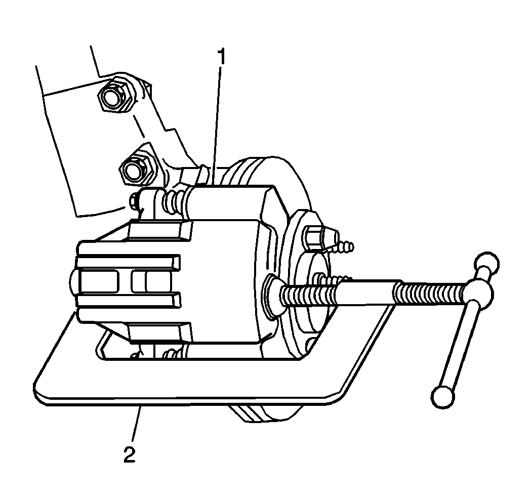
- Install a C-clamp (2) over the top of the brake caliper and against the back of the outboard brake pad.
- Tighten the C-clamp (2) until the brake caliper piston pushes into the brake caliper bore enough to slide the brake caliper (1) off of the rotor.
- Remove the C-clamp (2) from the brake caliper.
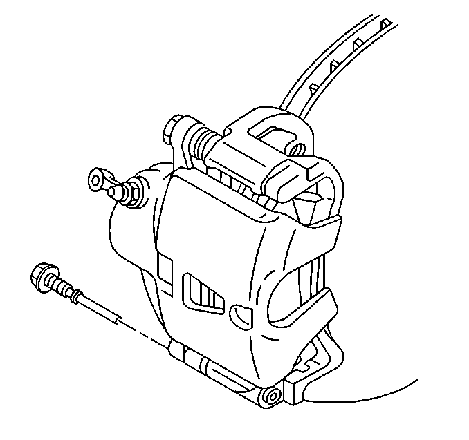
- Remove the lower brake caliper guide point.
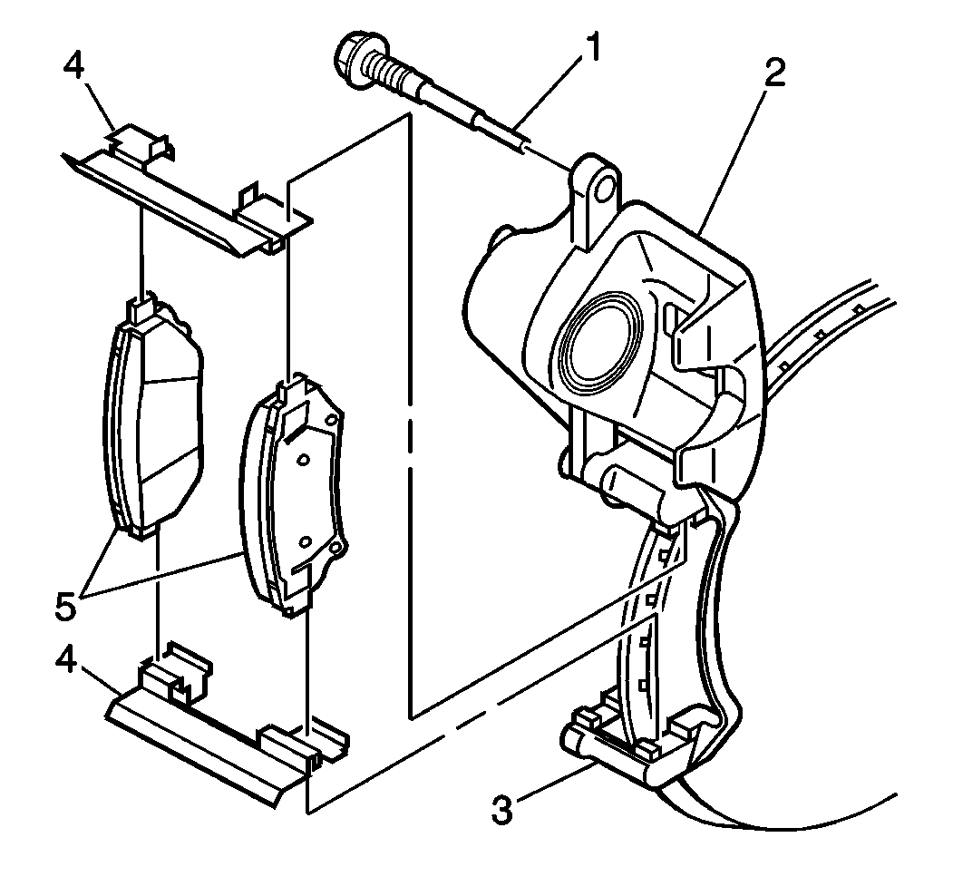
- Rotate the brake caliper (2) upward in order to access the brake pads.
- Remove the brake pads (5) from the brake caliper bracket (3).
- Remove the brake pad retainers (4) from the brake caliper bracket (3).
- Install a C-clamp over the brake caliper and against the block of wood or the old brake pad.
- Tighten the C-clamp until the brake caliper piston pushes completely into the brake caliper bore.
- Remove the C-clamp from the brake caliper.
- Inspect the brake caliper guide pin boots (4) for the following conditions:
- Inspect the brake caliper piston boot (1) for the following conditions:
- Inspect the brake caliper guide pins for corrosion or damage. If corrosion is found, use new parts, including bushings, when installing the brake caliper. Do not attempt to polish away corrosion.
Notice: Support the brake caliper with heavy mechanic wire, or equivalent, whenever it is separated from its mount and the hydraulic flexible brake hose is still connected. Failure to support the caliper in this manner will cause the flexible brake hose to bear the weight of the caliper, which may cause damage to the brake hose and in turn may cause a brake fluid leak.
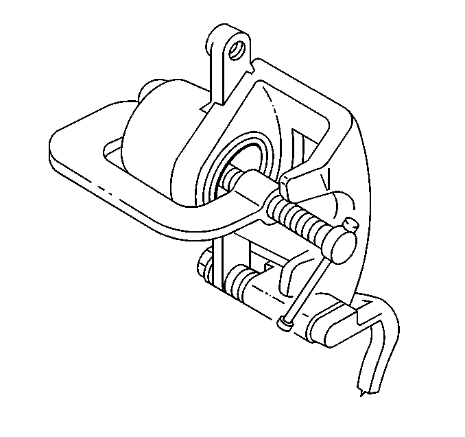
Important: Insert a block of wood or the old brake pad brake between the C-clamp and the brake caliper piston in order to prevent damage to the brake caliper piston and the brake caliper piston boot.
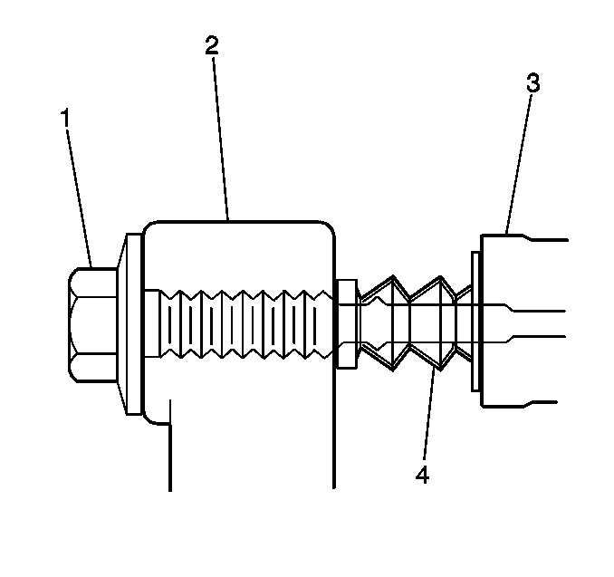
| • | Cuts |
| • | Tears |
| • | Deterioration |
| • | Replace the brake caliper guide pin boots if damage exists. Refer to Front Brake Caliper Bracket Replacement . |
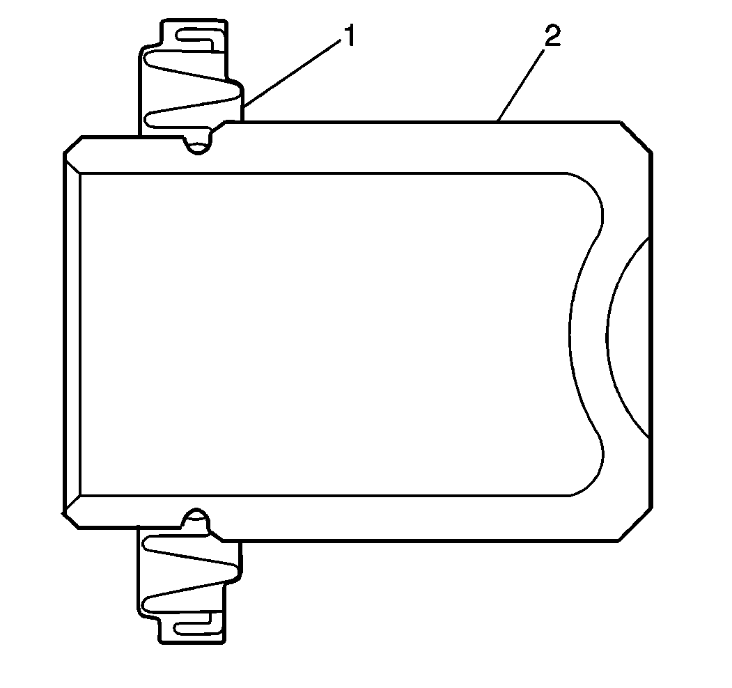
| • | Cuts |
| • | Tears |
| • | Leaking |
| • | Deterioration |
| • | Replace the brake caliper piston boot if damage exists. Refer to Front Brake Caliper Overhaul . |
Installation Procedure
- If you are installing new brake pads, use a C-clamp in order to compress the piston to the bottom of the caliper bore. Use the old brake pad, a metal plate or a wooden block across the face of the piston in order to protect the piston and the caliper boot.
- Install the two brake pad retainers (4) to the caliper bracket (3).
- Install the brake pads (5) over the brake pad retainers (4) and onto the caliper bracket (3).
- Lubricate the brake caliper guide pin (1) and the guide pin boot with High Temp Brake Silicone Lube, or equivalent.
- Pivot the caliper down onto the pads.
- Install the lower caliper guide pin.
- Remove the 2 wheel nuts securing the rotor to the hub and bearing.
- Install the tire and wheel. Tire and Wheel Removal and Installation .
- Lower the vehicle.
- Fill the master cylinder to the proper level with new clean brake fluid. Refer to Master Cylinder Reservoir Filling .
- Pump the brake pedal 3/4 of a full stroke as many times as necessary to obtain a firm brake pedal.
- Burnish the pads and the rotors. Refer to Brake Pad and Rotor Burnishing .
Important: Use denatured alcohol to clean the outside surface of caliper boot before installing new brake pads.

Important: Ensure that the wear sensor is positioned at the trailing edge (upward) of the outer pad during forward wheel rotation.
Notice: Use care to avoid damaging pin boot when rotating caliper.
Notice: Refer to Fastener Notice in the Preface section.

Tighten
Tighten the caliper guide pin to 54 N·m (40 lb ft).
