DTC P0711 3.5L
Circuit Description
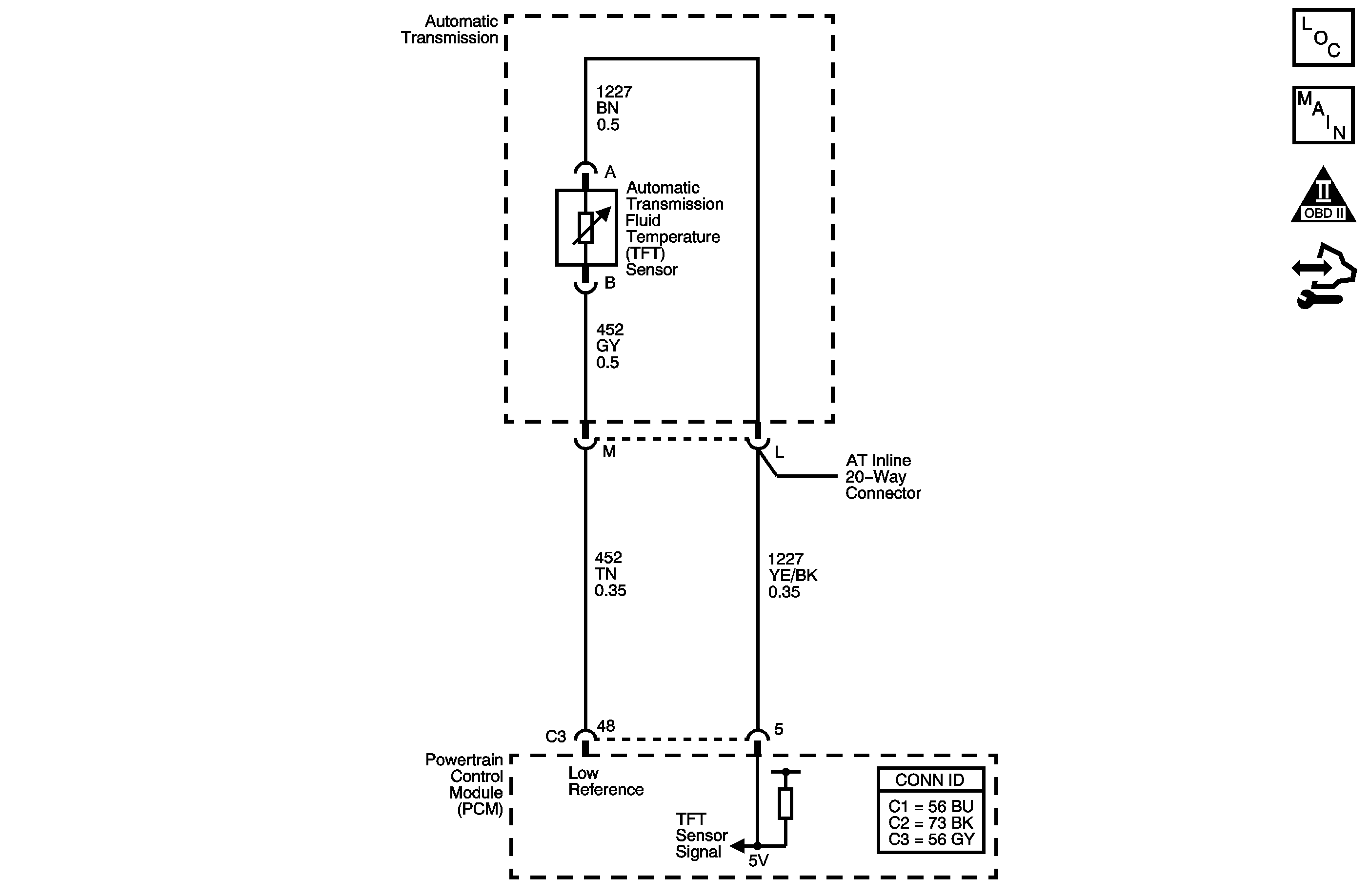
The automatic transmission fluid temperature (TFT) sensor is a negative coefficient thermistor. When the transmission fluid is cold, the sensor resistance is high. As the transmission fluid warms up, the sensor resistance decreases. This diagnostic monitors the TFT sensor circuit. The circuit may be functional but not in the normal operating range. This diagnostic indicates stuck, erratic, intermittent, or skewed values, resulting in reduced system performance. The TFT sensor range is -40 to +151°C (-40 to +304°F).
If the powertrain control module (PCM) detects an intermittent voltage or no voltage change in the TFT sensor circuit, then DTC P0711 sets. DTC P0711 is a type C DTC.
DTC Descriptor
This diagnostic procedure supports the following DTC:
DTC P0711 Transmission Fluid Temperature (TFT) Sensor Performance
Conditions for Running the DTC
| • | No ECT DTC P0117 or P0118. |
| • | No VSS DTC P0502 or P0503. |
| • | No ISS DTC P0716 or P0717. |
| • | The engine run time is 5 minutes or more. |
| • | The engine coolant temperature is at least 84°C (183°F) and has changed 55°C (99°F) since start up. |
| • | The TFT sensor voltage is 0.2-4.92 volts. |
| • | The transmission fluid temperature at start-up is -40 to +21°C (-40 to +69°F). |
| • | The vehicle speed is 8 km/h (5 mph) or more for at least 6 minutes and 49 seconds cumulative. |
| • | The TCC slip is 80 RPM or more for at least 6 minutes and 49 seconds cumulative. |
Conditions for Setting the DTC
DTC P0711 sets when one of the following conditions occurs:
Condition 1
The change in transmission fluid temperature is 1.5°C (2.7°F) or less since start-up for at least 6 minutes and 49 seconds continuous.
Condition 2
The change in transmission fluid temperature is 20°C (36°F) or more 14 times within 7 seconds.
Action Taken When the DTC Sets
| • | The PCM does not illuminate the malfunction indicator lamp (MIL). |
| • | The PCM freezes transmission adaptive functions. |
| • | The PCM calculates a default TFT from the ECT sensor and the IAT sensor. |
| • | The PCM records the operating conditions when the Conditions for Setting the DTC are met. The PCM stores this information as Failure Records. |
| • | The PCM stores DTC P0711 in PCM history. |
Conditions for Clearing the DTC
| • | A scan tool can clear the DTC. |
| • | The PCM clears the DTC from PCM history if the vehicle completes 40 warm-up cycles without a non-emission related diagnostic fault occurring. |
| • | The PCM cancels the DTC default actions when the fault no longer exists and the DTC passes. |
Test Description
The numbers below refer to the step numbers on the diagnostic table.
-
This step attempts to repeat the condition that set the DTC.
-
This step attempts to repeat the condition in the engine wiring harness.
-
This step determines if a condition exists with the PCM or TFT sensor.
Step | Action | Value(s) | Yes | No | ||||
|---|---|---|---|---|---|---|---|---|
1 | Did you perform the Diagnostic System Check - Vehicle? | -- | Go to Step 2 | |||||
2 | Did you perform the Transmission Fluid Checking Procedure? | -- | Go to Step 3 | Go to Transmission Fluid Check | ||||
Important: Before clearing the DTCs, use the scan tool in order to record the Failure Records for reference. Using the Clear DTC Information function will erase the stored Failure Records from the PCM. Did you record the temperatures? | -- | Go to Step 4 | -- | |||||
4 | Did the transmission fluid temperature rise more than the specified value? | 1.5°C (2.7°F) | Go to Step 5 | Go to Step 6 | ||||
Refer to Automatic Transmission Inline 20-Way Connector End View . Does the transmission fluid temperature change by more than the specified value? | 20°C (36°F) | Go to Step 7 | Go to Step 9 | |||||
Does the transmission fluid temperature change more than the specified value when the AT inline 20-way connector is disconnected? | 1.5°C (2.7°F) | Go to Step 12 | Go to Step 13 | |||||
7 | Test the signal circuit of the TFT sensor for an intermittent open or short to ground between the PCM and the AT inline 20-way connector. Refer to: Did you find and correct the condition? | -- | Go to Step 14 | Go to Step 8 | ||||
8 | Test the low reference circuit of the TFT sensor for an intermittent open or short to ground between the PCM and the AT inline 20-way connector. Refer to: Did you find and correct the condition? | -- | Go to Step 14 | Go to Step 13 | ||||
9 | Test the signal circuit of the TFT sensor for an intermittent open or short to ground between the AT inline 20-way connector and the TFT sensor. Refer to: Did you find the condition? | -- | Go to Step 11 | Go to Step 10 | ||||
10 | Test the low reference circuit of the TFT sensor for an intermittent open or short to ground between the AT inline 20-way connector and the TFT sensor. Refer to: Did you find the condition? | -- | Go to Step 11 | Go to Step 12 | ||||
11 | Replace the automatic transmission wiring harness assembly. Refer to Wiring Harness Replacement . Did you complete the replacement? | -- | Go to Step 14 | -- | ||||
12 | Replace the TFT sensor. Refer to Fluid Temperature Sensor Replacement . Did you complete the replacement? | -- | Go to Step 14 | -- | ||||
13 | Replace the PCM. Refer to Control Module References for replacement, setup and programming. Did you complete the replacement? | -- | Go to Step 14 | -- | ||||
14 | Perform the following procedure in order to verify the repair:
Has the test run and passed? | -- | Go to Step 15 | Go to Step 2 | ||||
15 | With a scan tool, observe the stored information, capture info and DTC info. Does the scan tool display any DTCs that you have not diagnosed? | -- | System OK |
DTC P0711 3.9L
Circuit Description
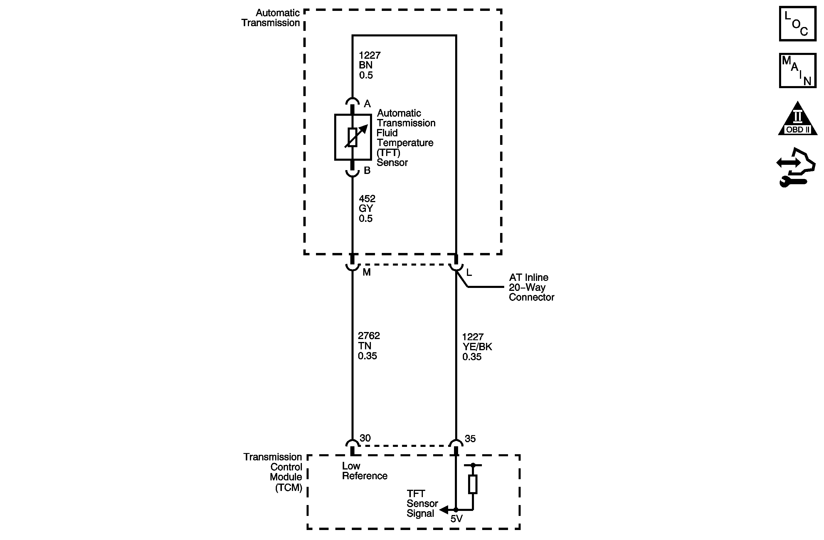
The automatic transmission fluid temperature (TFT) sensor is a negative coefficient thermistor. When the transmission fluid is cold, the sensor resistance is high. As the transmission fluid warms up, the sensor resistance decreases. This diagnostic monitors the TFT sensor circuit. The circuit may be functional but not in the normal operating range. This diagnostic indicates stuck, erratic, intermittent, or skewed values, resulting in reduced system performance. The TFT sensor range is -40 to +151°C (-40 to +304°F).
If the TCM detects an intermittent voltage or no voltage change in the TFT sensor circuit, then DTC P0711 sets. DTC P0711 is a type C DTC.
DTC Descriptor
This diagnostic procedure supports the following DTC:
DTC P0711 Transmission Fluid Temperature (TFT) Sensor Performance
Conditions for Running the DTC
| • | No ECT DTC P0117 or P0118. |
| • | No ISS DTC P0716 or P0717. |
| • | No OSS DTC P0722 or P0723. |
| • | DTC P0711 has not passed this ignition cycle. |
| • | The engine coolant temperature is at least 70°C (158°F) and has changed by 55°C (99°F) since start up for Condition 1 and Condtion 2. |
| • | The transmission fluid temperature is -39°C to 149°C (38°F to 300°F). |
| • | The vehicle speed is 8 km/h (5 mph) or more for at least 5 minutes cumulative for Condition 1 and Condition 2. |
| • | The TCC slip is 120 RPM or more for at least 5 minutes cumulative for Condition 1. |
| • | The calc. throttle position is between 8 and 90 percent for Condition 3. |
| • | The engine torque is 50 N·m (37 lb ft) or more for Condition 3. |
| • | The vehicle speed is 8 km/h (5 mph) or more for Condition 3. |
| • | The engine speed is greater than 500 RPM for Condition 3. |
Conditions for Setting the DTC
DTC P0711 sets when one of the following conditions occurs:
Condition 1
The change in transmission fluid temperature is 2°C (4°F) or less when the TFT is -40°C to 21°C (-40°F to 68°F) at start up for 80 seconds.
Condition 2
The change in transmission fluid temperature is 2°C (4°F) when the TFT is 129°C to 150°C (264°F to 302°F) at start up for 80 seconds.
Condition 3
The change in transmission fluid temperature is 20°C (68°F) or less after a predetermined time.
Action Taken When the DTC Sets
| • | The TCM does not request the ECM to illuminate the malfunction indicator lamp (MIL). |
| • | The TCM freezes transmission adaptive functions. |
| • | The TCM calculates a default TFT from the ECT sensor and the IAT sensor. |
| • | The TCM records the operating conditions when the Conditions for Setting the DTC are met. The TCM stores this information as Failure Records. |
| • | The TCM stores DTC P0711 in TCM history. |
Conditions for Clearing the DTC
| • | A scan tool can clear the DTC. |
| • | The TCM clears the DTC from TCM history if the vehicle completes 40 warm-up cycles without a non-emission related diagnostic fault occurring. |
| • | The TCM cancels the DTC default actions when the fault no longer exists and the DTC passes. |
Test Description
The numbers below refer to the step numbers on the diagnostic table.
-
This step attempts to repeat the condition that set the DTC.
-
This step attempts to repeat the condition in the engine wiring harness.
-
This step determines if a condition exists with the TCM or TFT sensor.
Step | Action | Value(s) | Yes | No |
|---|---|---|---|---|
1 | Did you perform the Diagnostic System Check - Vehicle? | -- | Go to Step 2 | |
2 | Did you perform the Transmission Fluid Checking Procedure? | -- | Go to Step 3 | Go to Transmission Fluid Check |
Important: Before clearing the DTCs, use the scan tool in order to record the Failure Records for reference. Using the Clear Info function will erase the stored Failure Records from the TCM. Did you record the temperatures? | -- | Go to Step 4 | -- | |
4 | Did the transmission fluid temperature rise more than the specified value? | 2°C (3.6°F) | Go to Step 5 | Go to Step 6 |
Refer to Automatic Transmission Inline 20-Way Connector End View . Does the transmission fluid temperature change by more than the specified value? | 20°C (36°F) in 0.20 seconds | Go to Step 7 | Go to Step 9 | |
Does the transmission fluid temperature change more than the specified value when the AT inline 20-way connector is disconnected? | 1.5°C (2.7°F) | Go to Step 12 | Go to Step 13 | |
7 | Test the signal circuit of the TFT sensor for an intermittent open or short to ground between the TCM and the AT inline 20-way connector. Refer to: Did you find and correct the condition? | -- | Go to Step 14 | Go to Step 8 |
8 | Test the low reference circuit of the TFT sensor for an intermittent open or short to ground between the TCM and the AT inline 20-way connector. Refer to: Did you find and correct the condition? | -- | Go to Step 14 | Go to Step 13 |
9 | Test the signal circuit of the TFT sensor for an intermittent open or short to ground between the AT inline 20-way connector and the TFT sensor. Refer to: Did you find the condition? | -- | Go to Step 11 | Go to Step 10 |
10 | Test the low reference circuit of the TFT sensor for an intermittent open or short to ground between the AT inline 20-way connector and the TFT sensor. Refer to: Did you find the condition? | -- | Go to Step 11 | Go to Step 12 |
11 | Replace the automatic transmission wiring harness assembly. Refer to Wiring Harness Replacement . Did you complete the replacement? | -- | Go to Step 14 | -- |
12 | Replace the TFT sensor. Refer to Fluid Temperature Sensor Replacement . Did you complete the replacement? | -- | Go to Step 14 | -- |
13 | Replace the TCM. Refer to Control Module References for replacement, setup and programming. Did you complete the replacement? | -- | Go to Step 14 | -- |
14 | Perform the following procedure in order to verify the repair:
Has the test run and passed? | -- | Go to Step 15 | Go to Step 2 |
15 | With a scan tool, observe the stored information, capture info and DTC info. Does the scan tool display any DTCs that you have not diagnosed? | -- | System OK |
