SERVICE MANUAL UPDATE SEC. C13 CRANKCASE VENTILATION (PCV)

SUBJECT: SMU - REVISED SECTION C13, CRANKCASE VENTILATION
VEHICLES AFFECTED: 1992 "L,N" CARS WITH 2.3L ENGINE (VIN D,A,3)
This bulletin serves to update Section C13, Crankcase Ventilation, found in 6E3 "Driveability and Emissions" in the 1992 Service Manuals with 2.3L "N" (VIN D, A and 3) and "L1' (VIN A) applications.
Included in this update are procedures necessary to diagnose the Crankcase Ventilation Heater Assembly Circuit found on these applications.
SECTION C13 CRANKCASE VENTILATION
CONTENTS
General Description C13-1 On-Vehicle Service C13-1 Operation C13-1 Crankcase Ventilation Heater Results Of Incorrect Assembly C13-1 Operation C13-1 Diagnosis C13-1
GENERAL DESCRIPTION
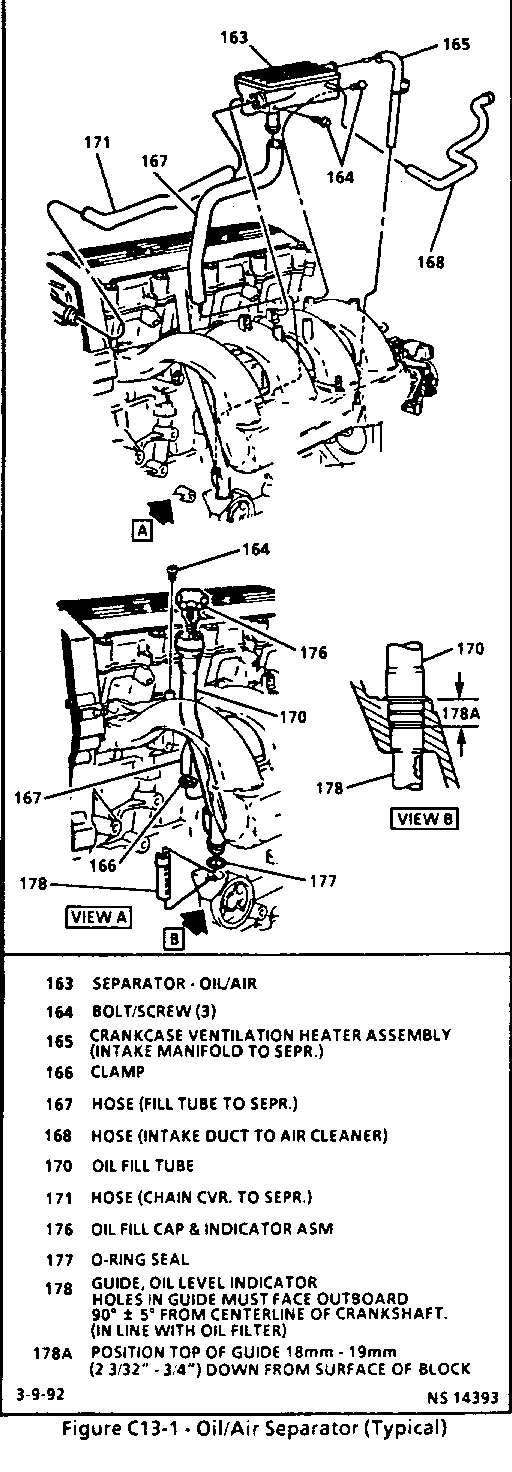
A crankcase ventilation system is used to provide scavenging of crankcase vapors. Blow-by gases are passed through a crankcase ventilation oil/air separator into the intake manifold. (Figure C13-1.) Incorporated in the crankcase ventilation system is a crankcase ventilation heater assembly. The assembly contains a heater (item #165) which is a Positive Temperature Coefficient device. The purpose of the heater is to prevent icing in the crankcase ventilation system.
OPERATION
The only flow through the oil/air separator is the combustion blow-by, as there is no fresh air inlet to the crankcase. Figure C13-1 illustrates the system and identifies by number the components of the system. The primary flow of blow-by into the separator is through a hose (item #171) from the timing chain housing. The oil/air separator causes oil, which may be suspended in the blow-by gases, to be separated and drain back to the crankcase through a hose (item #167) to the oil fill tube. This hose may also flow some of the blow-by gases into the separator under certain conditions. The upper smaller nipple connects through a hose (item #165) to manifold vacuum. The heater assembly inside the hose warms when the ignition is turned "ON" in order to prevent icing. This hose draws the gases from the separator under high manifold vacuum (idle or steady speed) conditions. There is a 1.52 mm (.060") orifice inside the smaller nipple to restrict flow through the hose (item #165). The lower, larger nipple, connects through a hose (item #168), to a rubber connector (item #179) to a tube (item #2), to the air intake duct from the air cleaner. This hose draws gases from the separator primarily under high air flow (high RPM), low vacuum conditions.
RESULTS OF INCORRECT OPERATION
A plugged oil/air separator or hose may cause:
o Oil leaks due to high crankcase pressure.
o Sludge in engine due to inadequate scavenging of crankcase vapors.
A leaking oil/air separator or hose could cause:
o High idle speed due to vacuum leak.
o Oil leaks from separator or hose.
DIAGNOSIS
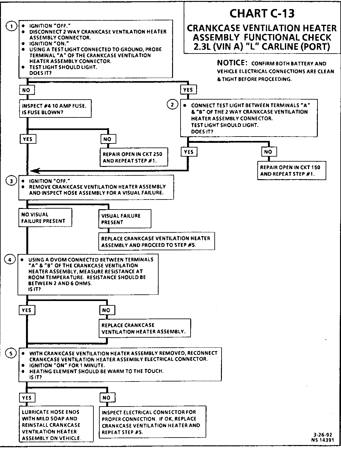
The following C-13 Chart is used to diagnose the crankcase ventilation heater assembly electrical system. If oil sludging or leaks are noted, verify that the CV oil/air separator is not plugged. This may be done by verifying that smaller nipple (connected to hose item #165) can be blown through or that 1.52 mm (.060") plug gage will fit into the orifice inside the nipple. If plugged, replace the CV oil/air separator assembly.
ON-VEHICLE SERVICE
CRANKCASE VENTILATION HEATER ASSEMBLY
Remove or Disconnect
1. Negative battery cable.
2. Electrical connector.
3. Crankcase ventilation heater assembly.
4. Hoses from crankcase ventilation heater assembly.
NOTICE: When installing hoses, apply a small film of soap to the inside edges of the hose prior to installation.
Install or Connect
1. Hoses to crankcase ventilation heater assembly.
2. Crankcase ventilation heater assembly to oil/air separator and to intake manifold.
3. Electrical connector to crankcase ventilation heater assembly.
4. Negative battery cable.
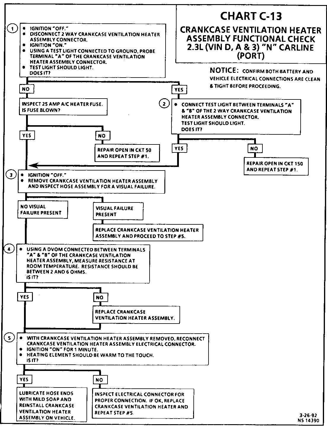
CHART C-13
CRANKCASE VENTILATION H EATER ASSEMBLY FUNCTIONAL CHECK 2.3L (VIN D, A & 3) "N" CARLINE (PORT) -----------------------------------------------------------------------------
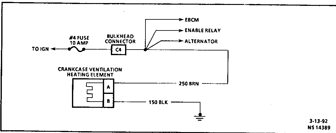
Circuit Description:
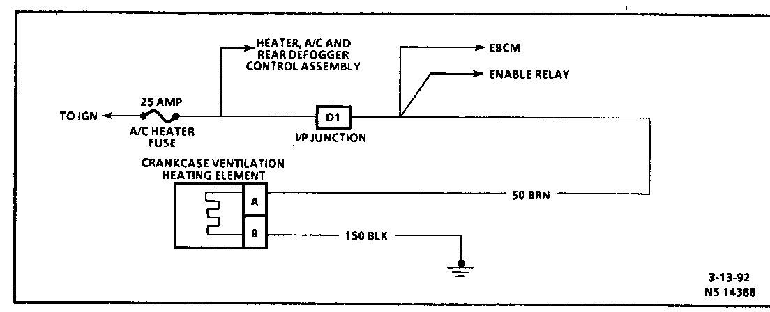
The crankcase ventilation heater assembly is used to prevent icing in the crankcase ventilation system. The heating element inside the vent hose is used to prevent icing from the oil/air separator to the intake manifold.
The heating element consists of two parallel wires that extend the length of the vent hose. One wire supplies the current when the ignition is turned "ON" while the second wire provides a constant path to ground.
Although the wires are not physically attached, the material between the two wires is conductive. Current is passed through the material between the wires. As the material is heated, electrical resistance increases and current flow decreases. When the material is cooled, electrical resistance decreases, current flow and heat output increases.
By this means, the temperature of the heating element is controlled to maintain approximately 115 degrees Fahrenheit.
Test Description: Number(s) below refer to circled number(s) on the diagnostic chart.
1. This step verifies voltage is present to the crankcase ventilation heater assembly system.
2. This step insures a good path to ground in CKT 150.
3. This step identifies a visual failure.
4. This step identifies an open, or out of range crankcase ventilation heater element.
5. This confirms that the crankcase ventilation heating element is operational and is functioning properly.
Diagnostic Aids:
Check to insure that both battery and associated vehicle electrical connections are clean & tight.
SECTION C13 CRANKCASE VENTILATION
CONTENTS
General Description C13-1 On-Vehicle Service C13-1 Operation C13-1 Crankcase Ventilation Heater Results Of Incorrect Assembly C13-1 Operation C13-1 Diagnosis C13-1
GENERAL DESCRIPTION
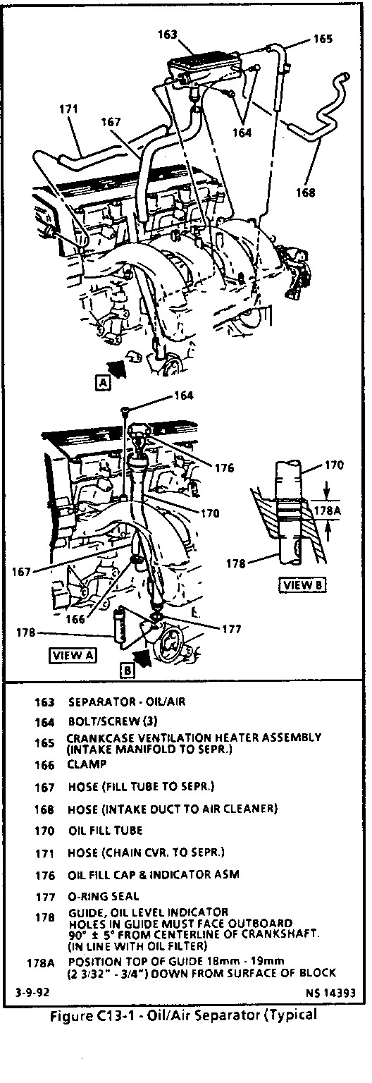
A crankcase ventilation system is used to provide scavenging of crankcase vapors. Blow-by gases are passed through a crankcase ventilation oil/air separator into the intake manifold. (Figure C13-1.) Incorporated in the crankcase ventilation system is a crankcase ventilation heater assembly. The assembly contains a heater (item #165) which is a Positive Temperature Coefficient device. The purpose of the heater is to prevent icing in the crankcase ventilation system.
OPERATION
The only flow through the oil/air separator is the combustion blow-by, as there is no fresh air inlet to the crankcase. Figure C13-1 illustrates the system and identifies by number the components of the system. The primary flow of blow-by into the separator is through a hose (item #171) from the timing chain housing. The oil/air separator causes oil, which may be suspended in the blow-by gases, to be separated and drain back to the crankcase through a hose (item #167) to the oil fill tube. This hose may also flow some of the blow-by gases into the separator under certain conditions. The upper smaller nipple connects through a hose (item #165) to manifold vacuum. The heater assembly inside the hose warms when the ignition is turned "ON" in order to prevent icing. This hose draws the gases from the separator under high manifold vacuum (idle or steady speed) conditions. There is a 1.52 mm (.060") orifice inside the smaller nipple to restrict flow through the hose (item #165). The lower, larger nipple, connects through a hose (item #168), to a rubber connector (item #179) to a tube (item #2), to the air intake duct from the air cleaner. This hose draws gases from the separator primarily under high air flow (high rpm), low vacuum conditions.
RESULTS OF INCORRECT OPERATION
A plugged oil/air separator or hose may cause:
o Oil leaks due to high crankcase pressure.
o Sludge in engine due to inadequate scavenging of crankcase vapors.
A leaking oil/air separator or hose could cause:
o High idle speed due to vacuum leak.
o Oil leaks from separator or hose.
DIAGNOSIS
The following C-13 Chart is used to diagnose the crankcase ventilation heater assembly electrical system. If oil sludging or leaks are noted, verify that the CV oil/air separator is not plugged. This may be done by verifying that smaller nipple (connected to hose item #165) can be blown through or that 1.52 mm (.060") plug gage will fit into the orifice inside the nipple. If plugged, replace the CV oil/air separator assembly.
ON-VEHICLE SERVICE
CRANKCASE VENTILATION HEATER ASSEMBLY
Remove or Disconnect
1. Negative battery cable.
2. Electrical connector.
3. Crankcase ventilation heater assembly.
4. Hoses from crankcase ventilation heater assembly.
NOTICE: When installing hoses, apply a small film of soap to the inside edges of the hose prior to installation.
Install or Connect
1. Hoses to crankcase ventilation heater assembly.
2. Crankcase ventilation heater assembly to oil/air separator and to intake manifold.
3. Electrical connector to crankcase ventilation heater assembly.
4. Negative battery cable.
CHART C-13
CRANKCASE VENTILATION HEATER ASSEMBLY FUNCTIONAL CHECK 2.3L (VIN A) "L" CARLINE (PORT) ----------------------------------------------------------------------------- Circuit Description:
The crankcase ventilation heater assembly is used to prevent icing in the crankcase ventilation system. The heating element inside the vent hose is used to prevent icing from the oil/air separator to the intake manifold.
The heating element consists of two parallel wires that extend the length of the vent hose. One wire supplies the current when the ignition is turned "ON" while the second wire provides a constant path to ground.
Although the wires are not physically attached, the material between the two wires is conductive. Current is passed through the material between the wires. As the material is heated, electrical resistance increases and current flow decreases. When the material is cooled, electrical resistance decreases, current flow and heat output increases.
By this means, the temperature of the heating element is controlled to maintain approximately 115 degrees Fahrenheit.
Test Description: Number(s) below refer to circled number(s) on the diagnostic chart.
1. This step verifies voltage is present to the crankcase ventilation heater assembly system.
2. This step insures a good path to ground in CKT 150.
3. This step identifies a visual failure.
4. This step identifies an open, or out of range crankcase ventilation heater element.
5. This confirms that the crankcase ventilation heater element is operational and is functioning properly.
Diagnostic Aids:
Check to insure that both battery and associated vehicle electrical connections are clean & tight.
General Motors bulletins are intended for use by professional technicians, not a "do-it-yourselfer". They are written to inform those technicians of conditions that may occur on some vehicles, or to provide information that could assist in the proper service of a vehicle. Properly trained technicians have the equipment, tools, safety instructions and know-how to do a job properly and safely. If a condition is described, do not assume that the bulletin applies to your vehicle, or that your vehicle will have that condition. See a General Motors dealer servicing your brand of General Motors vehicle for information on whether your vehicle may benefit from the information.
