SERVICE MANUAL UPDATE-SEC.7A AUTO. TRANSAXLE REMOVAL/INSTAL

SUBJECT: SMU - SECTION 7A - AUTOMATIC TRANSAXLE REMOVAL AND INSTALLATION (NEW SERVICE PROCEDURE)
VEHICLES AFFECTED: 1992 "E" MODELS WITH 3800 ENGINE (VIN L)
This bulletin replaces the procedure to remove and install the automatic transaxle. This procedure should be inserted at page 7A-28 in the 1992 "E" Service Manual.
4T60E TRANSAXLE
Figures 1 through 4
Tools required:
o J 28467 Engine Support Fixture o J 28467-50 Engine Support Hook o J 34754 Inner Drive Joint Seal Protector o J 37292-A Axle Seal Protector
Removal
1. Raise hood and cover fenders.
2. Negative battery cable.
3. Air intake duct.
4. Cruise Control:
o Cable at throttle body o Vacuum hoses at servo o Servo assembly
5. Shift control linkage:
o Mounting bracket at transaxle o Lever at manual shaft
6. Wiring connectors at:
o Transaxle park/neutral position and backup lamp switch o Transaxle electrical connector o Vehicle speed sensor o Power steering pressure switch
7. Fuel pipe retainers.
8. Vacuum modulator hose at modulator.
9. Transaxle filler tube.
10. Power steering pressure lines:
o Pressure hose at steering gear o Return line at cooler
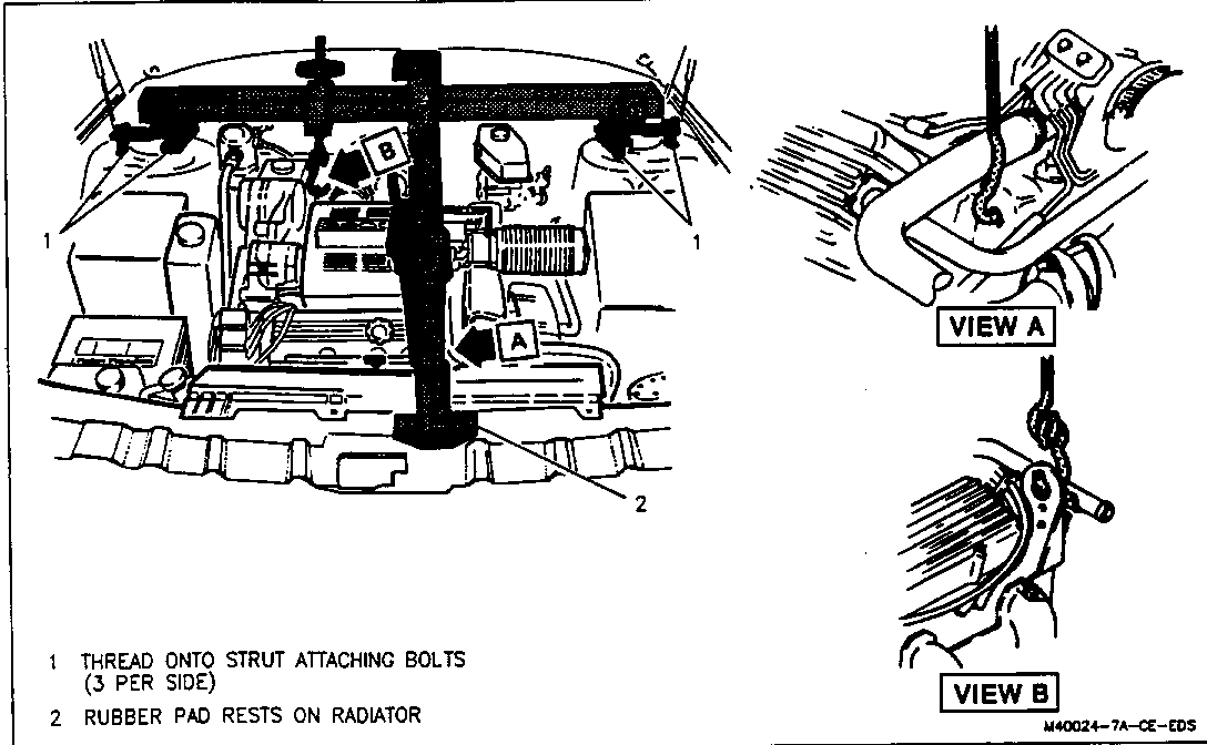
11. Install J 28467 engine support fixture.
o Be sure to "load" the support fixture by tightening the wing-nuts several turns to relieve tension on the frame and mounts.
CAUTION:
TO HELP AVOID PERSONAL INJURY WHEN A VEHICLE IS ON A HOIST, PROVIDE ADDITIONAL SUPPORT FOR THE VEHICLE AT THE OPPOSITE END FROM WHICH COMPONENTS ARE BEING REMOVED. THIS WILL REDUCE THE POSSIBILITY OF THE VEHICLE FALLING OFF THE HOIST.
12. Raise vehicle and suitably support. Refer to GENERAL INFORMATION (SECTION OA).
13. Both front tire and wheel assemblies.
14. Both wheel opening splash shields.
15. Rotate the steering gear intermediate shaft so that the steering gear stub shaft clamp bolt is accessible from the left wheel opening and remove clamp bolt.
16. Steering intermediate shaft from steering gear.
CAUTION:
FAILURE TO DISCONNECT THE INTERMEDIATE SHAFT FROM THE RACK AND PINION STUB SHAFT CAN RESULT IN DAMAGE TO THE STEERING GEAR AND/OR INTERMEDIATE SHAFT. THIS DAMAGE CAN CAUSE LOSS OF STEERING CONTROL WHICH COULD RESULT IN PERSONAL INJURY.
17. Both stabilizer links from struts.
18. Both tie rod cotter pins and nuts.
19. Separate both tie rods from steering knuckles.
20. Right and left front ball joint nuts.
21. Separate the right and left ball joints from steering knuckle. Refer to FRONT SUSPENSION (SECTION 3C).
NOTICE: Drive axle seal protector J 34754 should be modified and installed on any drive axle prior to service procedures on or near the drive axle. Failure to observe this can result in seal damage and possible joint failure. Refer to Section 4D for information on Tool J 34754 and for proper drive axle removal and handling procedures.
22. Drive axles. Refer to DRIVE AXLE (SECTION 4D).
o Remove drive axles from both the transaxle and the hub/knuckle assembly.
23. A/C splash shield from frame.
24. ABS modulator from bracket and support.
25. Transaxle cooler lines from transaxle.
26. Flywheel cover bolts and flywheel cover.
27. Flywheel to converter bolts.
o Mark flywheel to converter relationship to ensure proper reassembly.
28. Front exhaust pipe.
29. Left and right transaxle mount nuts and right engine mount nuts at frame.
30. Support frame.
31. Six frame mounting bolts.
32. Lower frame with steering gear attached.
33. Left transaxle mount and bracket from transaxle.
34. Right rear transaxle mount and bracket from transaxle.
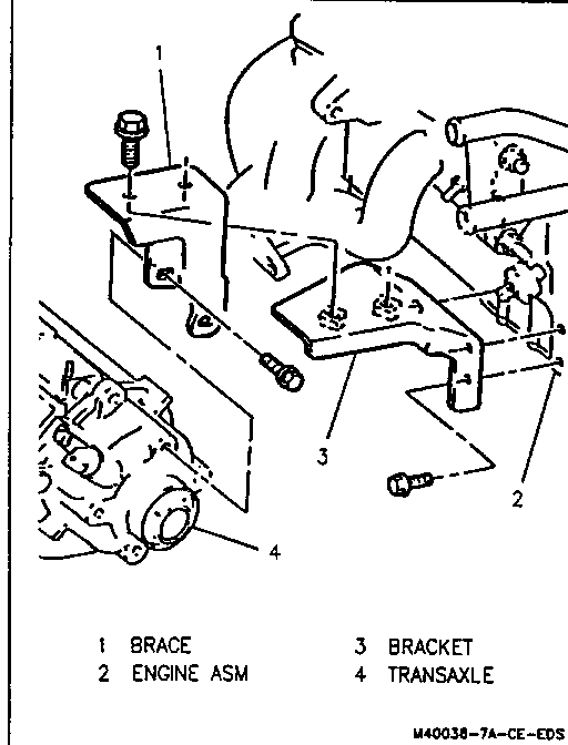
35. Engine to transaxle bracket.
36. Support transaxle with jack stand.
37. Transaxle to engine block bolts.
o One bolt is located between the transaxle case and the engine block and is installed in the opposite direction.
38. Lower transaxle assembly away from vehicle.
o Use care to avoid damaging right hand output shaft, shaft seal, hoses, lines and wiring.
INSTALLATION
To complete installation, observe the following assembly tips and reverse the removal procedure.
ASSEMBLY TIPS
o Use care when installing right side drive axle into the transaxle case. The splined shaft can easily damage the seal.
o Before installing right side drive axle, be sure to install tool J 37292-A axle seal protector. Refer to DRIVE AXLE (SECTION 4D).
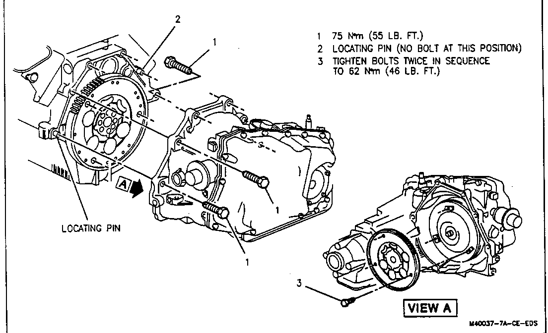
o Line up the flywheel to torque converter marks made at disassembly.
o Torque converter to flywheel bolts should always be tightened twice. The final torque should be 62 N.m (46 ft.1b.).
o Check adjustment of the shift cables.
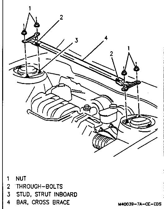
When installing cross brace to struts:
a. Place assembly on inboard strut studs.
b. Install strut stud nuts and torque to 24 N.m (18 ft. lb.).
c. Torque bar assembly through bolts to 28 N.m (21 ft. lb.).
o Check and adjust the fluid level as needed.
o Align the front end and bleed the power steering system.
o Road test and check for leaks.
o When installing transaxle to engine block brace, tighten brace to engine bolts first and brace to transaxle case last to avoid pulling transaxle out of line.
General Motors bulletins are intended for use by professional technicians, not a "do-it-yourselfer". They are written to inform those technicians of conditions that may occur on some vehicles, or to provide information that could assist in the proper service of a vehicle. Properly trained technicians have the equipment, tools, safety instructions and know-how to do a job properly and safely. If a condition is described, do not assume that the bulletin applies to your vehicle, or that your vehicle will have that condition. See a General Motors dealer servicing your brand of General Motors vehicle for information on whether your vehicle may benefit from the information.
