For 1990-2009 cars only
Tools Required
J 42640 Steering Column Anti-Rotation Pin
Removal Procedure
Notice: The steering column must be in the LOCK position before disconnecting
the following components:
• The steering column • The steering shaft coupling • The intermediate shaft
After disconnecting these components, do not move the front tires and
wheels. Failure to follow these procedures may cause improper
alignment of some components during installation and result in possible damage
to the SIR coil.
• The lower steering shaft
- Install J 42640 to the steering column.
- Turn the ignition OFF, with the wheel in a straight forward position.
- Raise and support the vehicle. Refer to Lifting and Jacking the Vehicle in General Information.
- Remove the left front tire and wheel. Refer to Tire and Wheel Removal and Installation in Tires and Wheels.
- Push the intermediate shaft lower seal up into the intermediate shaft upper seal in order to access to the intermediate shaft lower bolt.
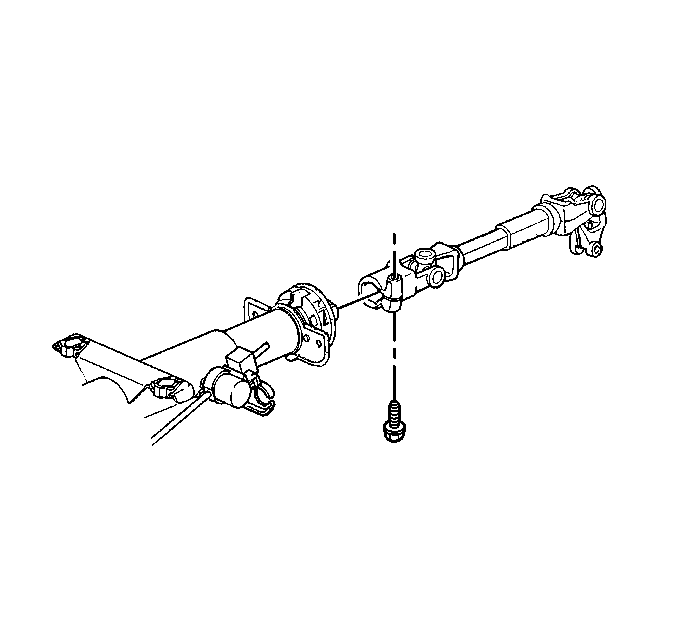
- Remove the intermediate shaft lower pinch bolt.
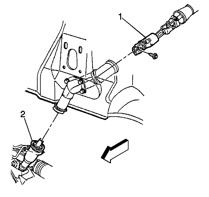
- Push the intermediate steering shaft (1) up in order to remove the intermediate steering shaft from the steering gear (2).
- Lower the vehicle.
- Remove the left closeout panel. Refer to Instrument Panel Insulator Panel Replacement - Left Side in Instrument Panel, Gages, and Console.
- Pull the intermediate steering shaft seal down off of the steering column in order to access the intermediate steering shaft upper bolt.
- Remove the intermediate shaft to steering column pinch bolt.
- Disconnect the intermediate shaft from the steering column.
- Remove the intermediate steering shaft through the inside of the vehicle.

Installation Procedure
- Install the intermediate steering shaft (1) through the intermediate steering shaft seal.
- Install the intermediate steering shaft (1) to the steering column.
- Install the intermediate steering shaft upper pinch bolt.
- Install the intermediate steering shaft to the steering column.
- Install the left closeout panel. Refer to Instrument Panel Insulator Panel Replacement - Left Side in Instrument Panel, Gages, and Console.
- Raise the vehicle. Refer to Lifting and Jacking the Vehicle in General Information.
- Connect the intermediate shaft (1) to the steering gear (2).
- Connect the intermediate steering shaft lower pinch bolt.
- Connect the intermediate steering shaft seal to the steering gear. Take care in aligning the seal the shaft clearance.
- Install the left front tire and wheel. Refer to Tire and Wheel Removal and Installation in Tires and Wheels.
- Lower the vehicle.
Notice: Refer to Fastener Notice in the Preface section.
Tighten
Tighten the intermediate steering shaft upper bolt to 48 N·m (35 lb ft).
Tighten
Tighten the intermediate steering shaft lower bolt to 48 N·m (35 lb ft).
