GM Service Manual Online
For 1990-2009 cars only
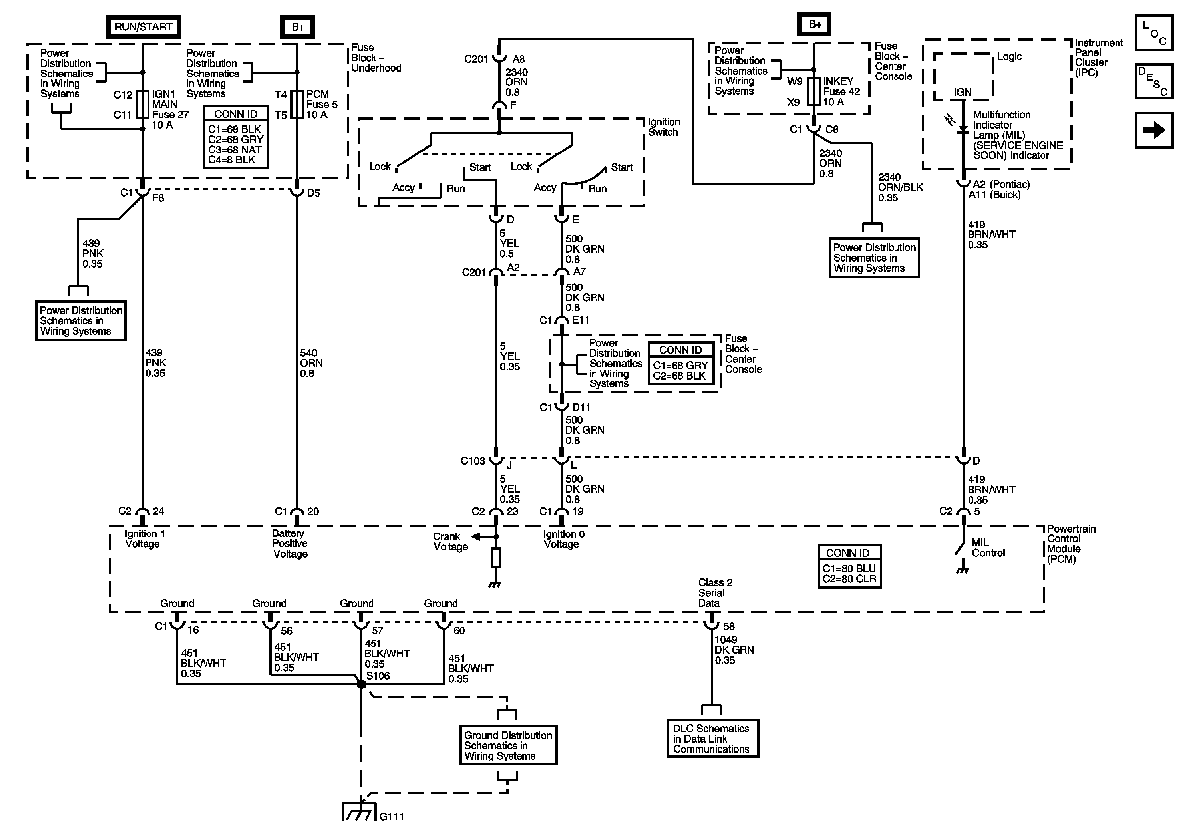
Figure 1:

Power, DLC, Ground, and MIL


Object Number: 623555  Size: FS
Master Electrical Component List
Powertrain Control Module Description
Ignition Control, KS
Fuse Block-Underhood Fuses: 32, 36, 9, 5 and 28
Fuse Block-Underhood Fuses: 27, 31 and 33 Fuse Block-Center Console Fuse: TURN SIG
Fuse Block-Underhood Fuse: 47 Fuse Block-Center Console Fuses: INKEY, KEY SOL, IGN 0 and FRT BLWR
Ground G111 Schematics
Cigar Lighter/Auxiliary Outlets Schematics-Buick
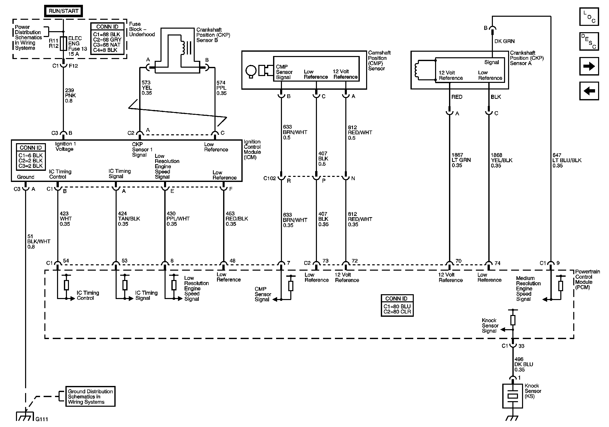
Figure 2:

Ignition Control, KS


Object Number: 623556  Size: FS
Master Electrical Component List
Electronic Ignition (EI) System Description
Fuel Injectors, Fuel Pump
Power, DLC, Ground, and MIL
Fuse Block-Underhood Fuses: 10, 6, 4, 13 and 30
Ground G111 Schematics
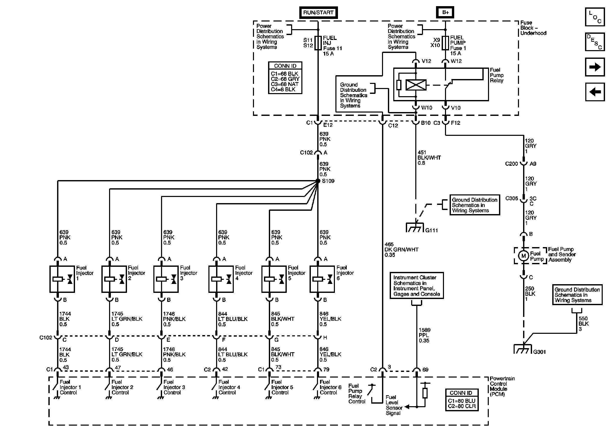
Figure 3:

Fuel Injectors, Fuel Pump


Object Number: 623568  Size: FS
Master Electrical Component List
Fuel System Description
HO2S
Ignition Control, KS
Fuse Block-Underhood Fuses: 11 and 7
Fuse Block-Underhood Buss Schematics
Ground G111 Schematics
Gauges
Ground G301 Schematics
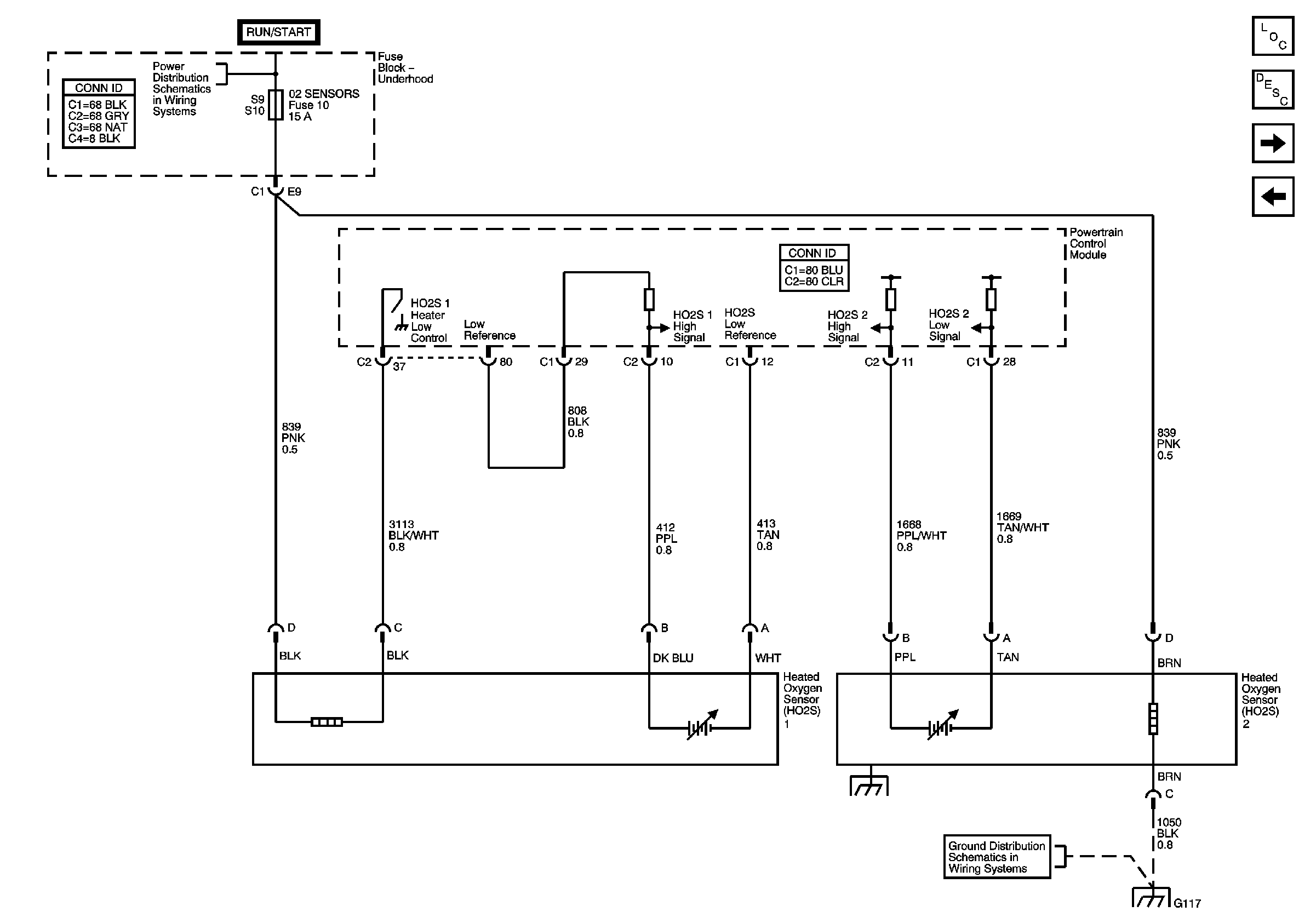
Figure 4:

HO2S


Object Number: 623583  Size: FS
Master Electrical Component List
Fuel System Description
EGR, EVAP
Fuel Injectors, Fuel Pump
Fuse Block-Underhood Fuses: 10, 6, 4, 13 and 30
Ground G117 Schematics
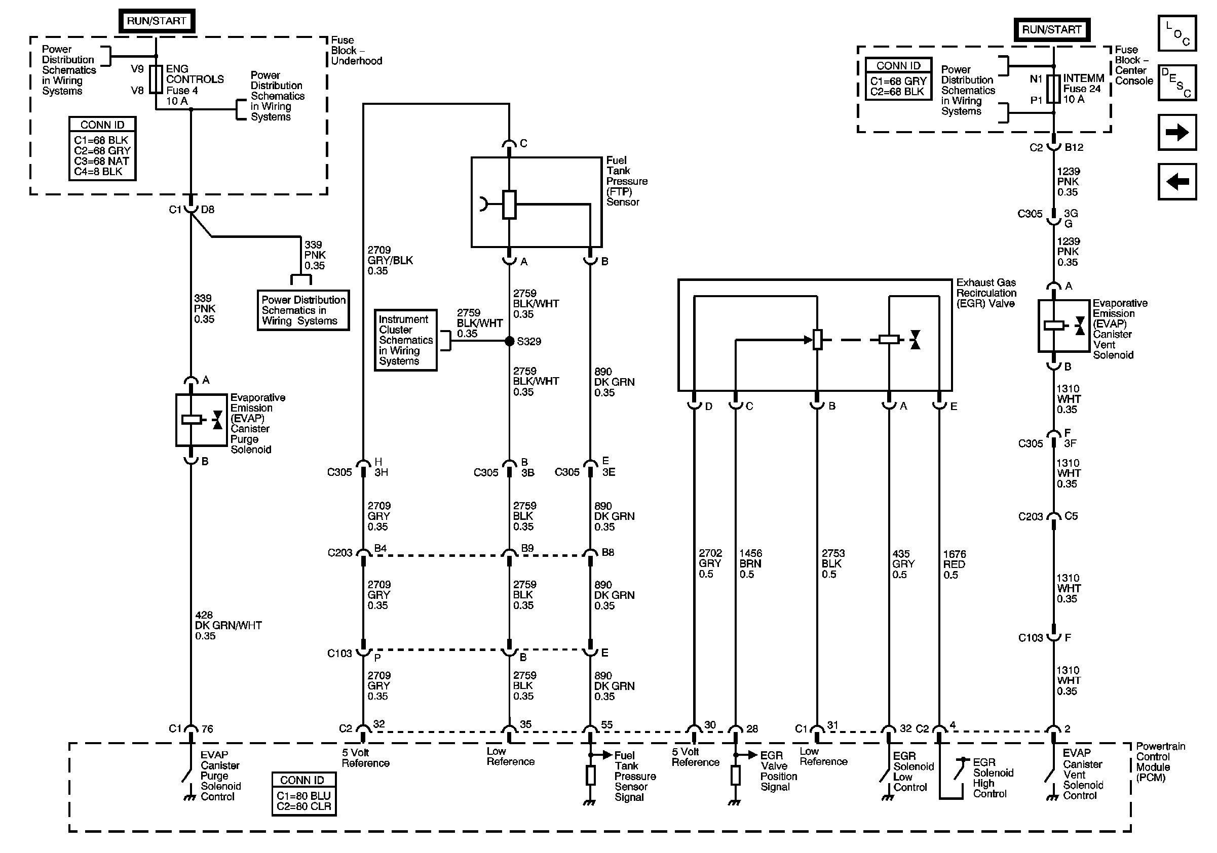
Figure 5:

EGR, EVAP


Object Number: 623603  Size: FS
Master Electrical Component List
Exhaust Gas Recirculation (EGR) System Description
Sensors
HO2S
Fuse Block-Underhood Fuses: 10, 6, 4, 13 and 30
Gauges
Fuse Block-Underhood Fuse: 19 Fuse Block-Center Console Fuses: IGN 1 MDL, SIR, INTEMM and BCM-ACCY
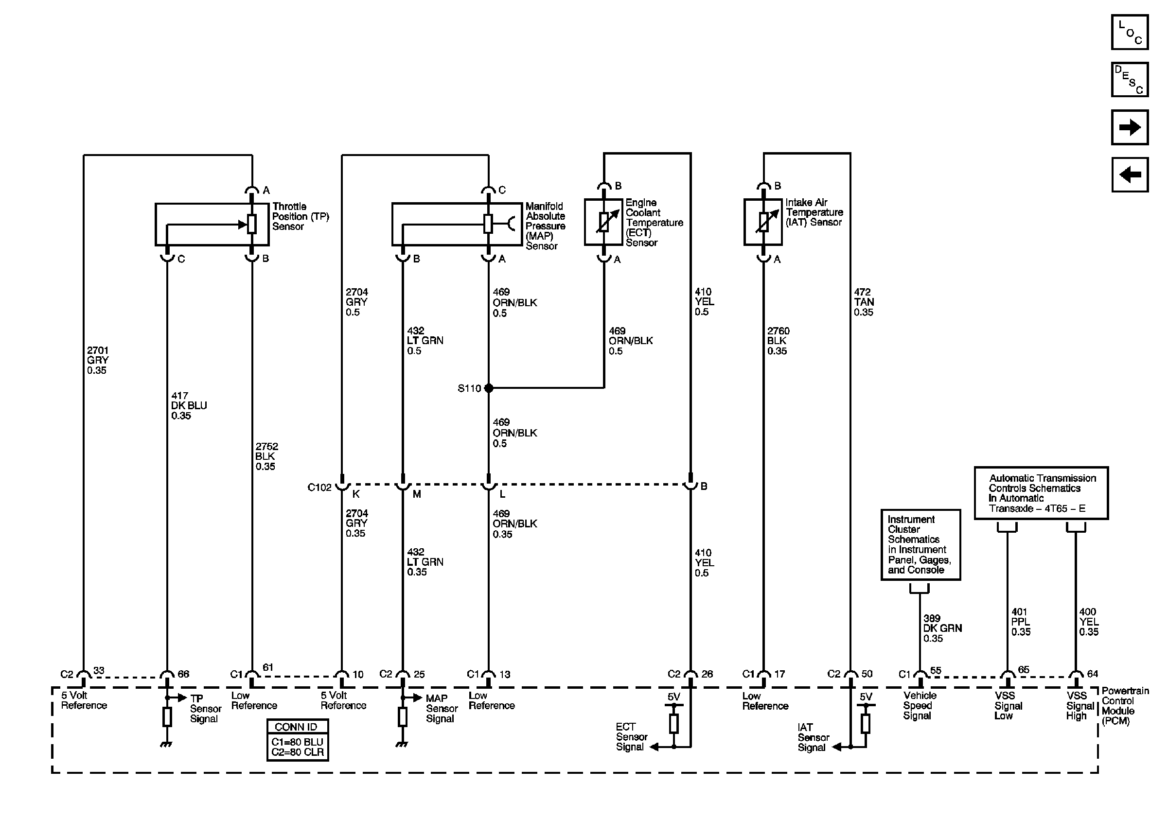
Figure 6:

Sensors


Object Number: 623580  Size: FS
Master Electrical Component List
Fuel System Description
AIR, IAC, and MAF
EGR, EVAP
Gauges
PNP Switch, VSS
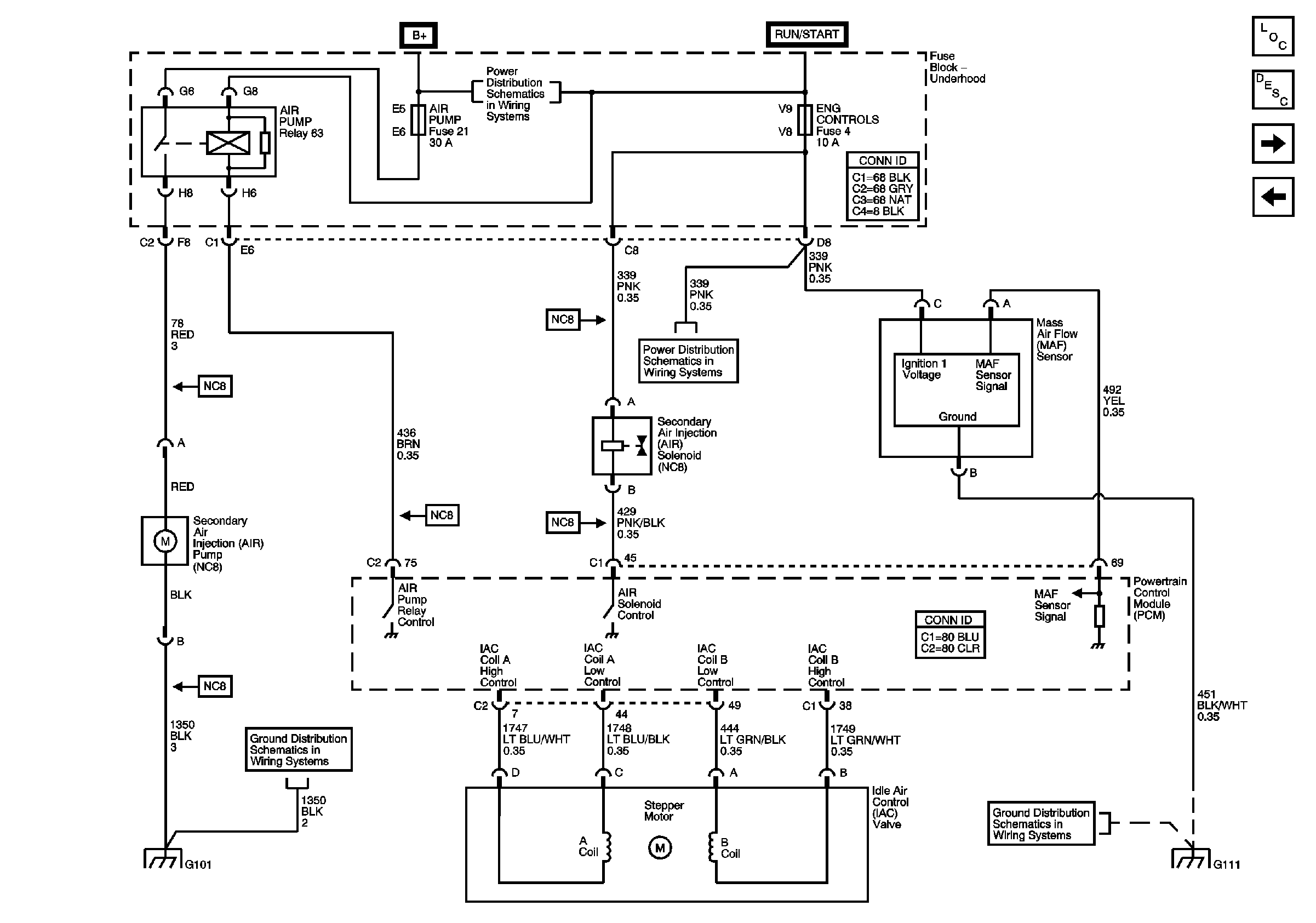
Figure 7:

AIR, IAC, and MAF


Object Number: 623590  Size: FS
Master Electrical Component List
Fuel System Description
PCM References (1 of 2)
Sensors
Fuse Block-Underhood Fuses: 10, 6, 4, 13 and 30
Ground G111 Schematics
Figure 8:

PCM References (1 of 2)


Object Number: 623607  Size: FS
Master Electrical Component List
Powertrain Control Module Description
PCM References (2 of 2)
AIR, IAC, and MAF
Cooling Fans
Power, Ground, Serial Data and Message Center
Charging Control, Indicator
Compressor Control
Engine Cranking
Differentail Controls AWD - GMT250
DLC, Indicators, and Traction Control Switch
Cruise Control Schematics
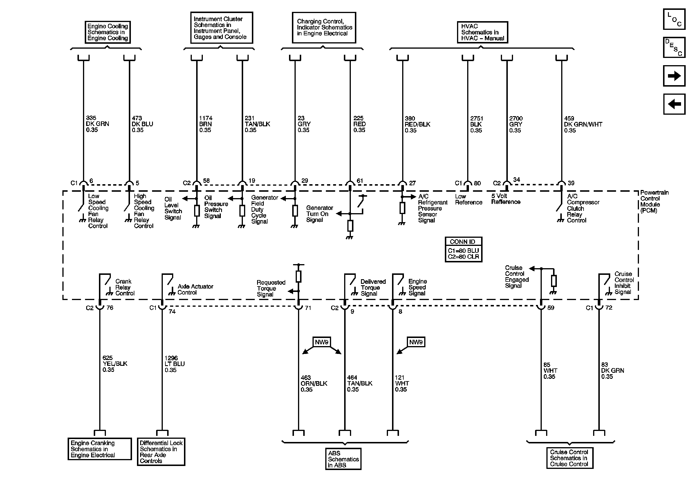
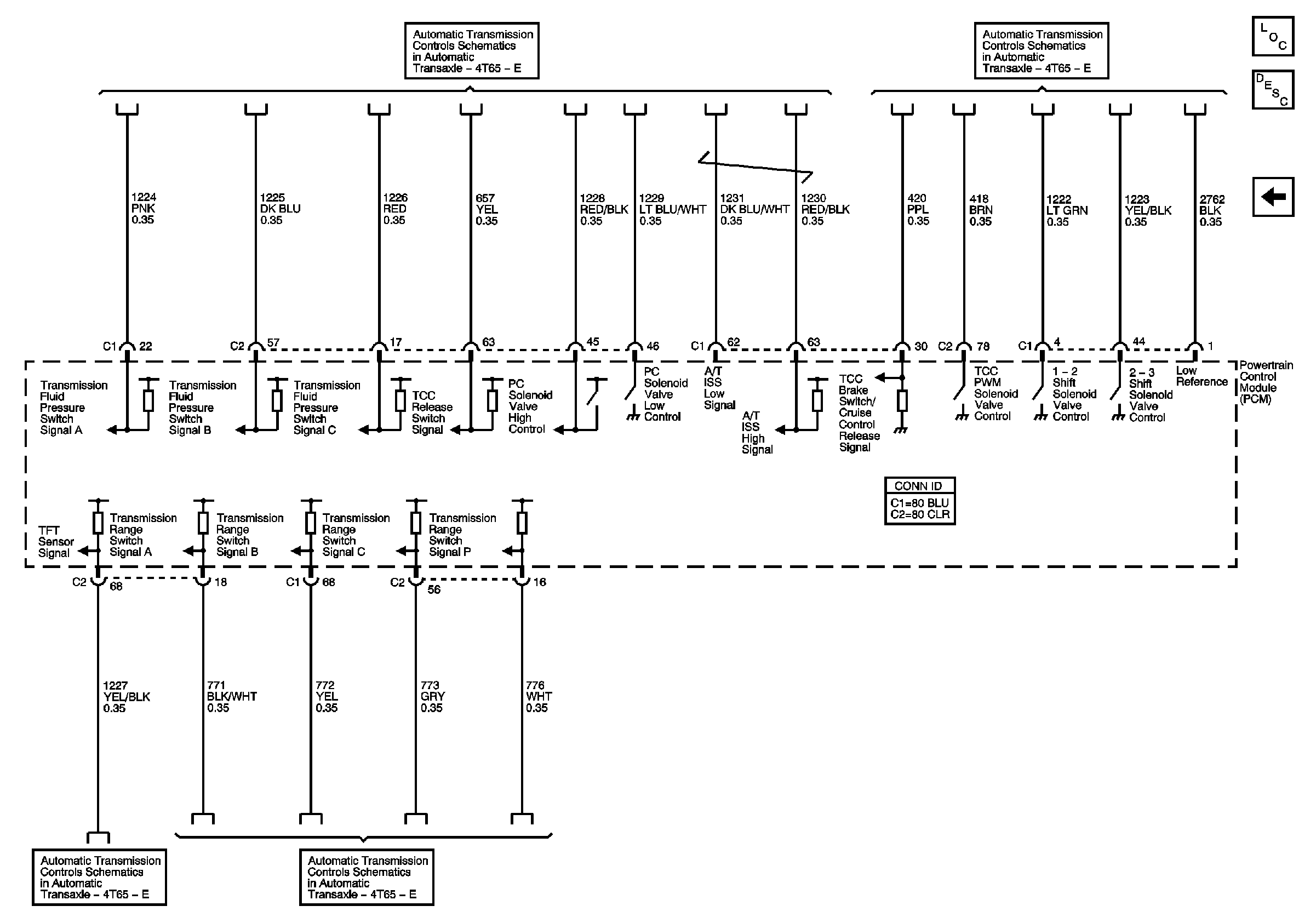
Figure 9:

PCM References (2 of 2)


Object Number: 623630  Size: FS
Master Electrical Component List
Powertrain Control Module Description
PCM References (1 of 2)
Switches, ISS and Pressure Control
SS, Stoplamps Switch, and TFT
PNP Switch, VSS