For 1990-2009 cars only
Removal Procedure
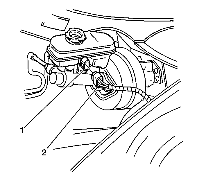
- Disconnect the electrical connector (2) from the fluid level sensor (1).
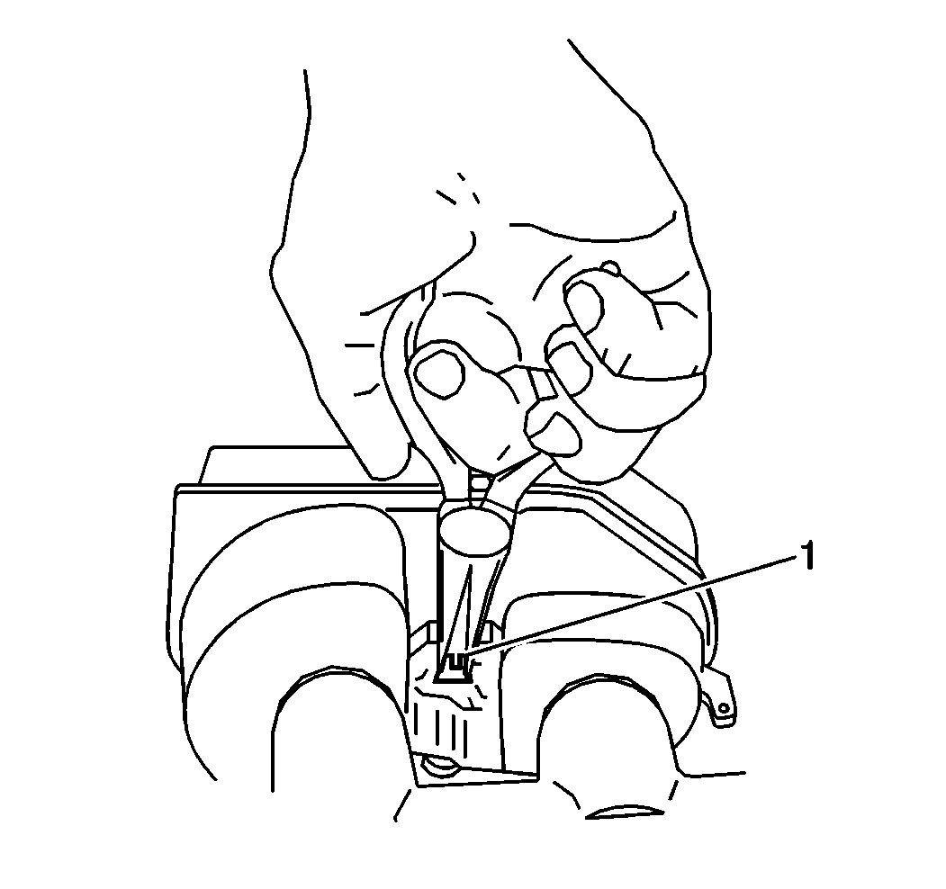
- Remove the fluid level sensor (1). Use needle nose pliers in order to compress the switch locking tabs at the outboard side of the master cylinder.


Installation Procedure
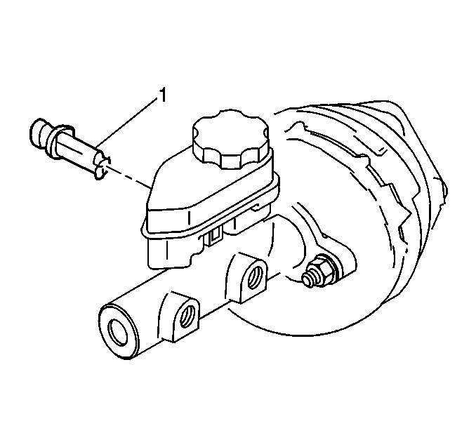
- Install the fluid level sensor (1) until the locking tabs snap into place.
- Connect the electrical connector to the fluid level sensor (1).

