For 1990-2009 cars only
Tools Required
J 24319-B Universal Steering Linkage Puller
Removal Procedure
- Raise and suitably support the vehicle. Refer to Lifting and Jacking the Vehicle .
- Remove the tire and wheel assembly. Refer to Tire and Wheel Removal and Installation .
- Remove the front wheel drive shaft bearing. Refer to Front Wheel Bearing and Hub Replacement .
- Remove the front lower control arm ball stud. Refer to Lower Control Arm Replacement .
- Remove the outer tie rod end from the steering knuckle. Refer to Rack and Pinion Outer Tie Rod End Replacement .
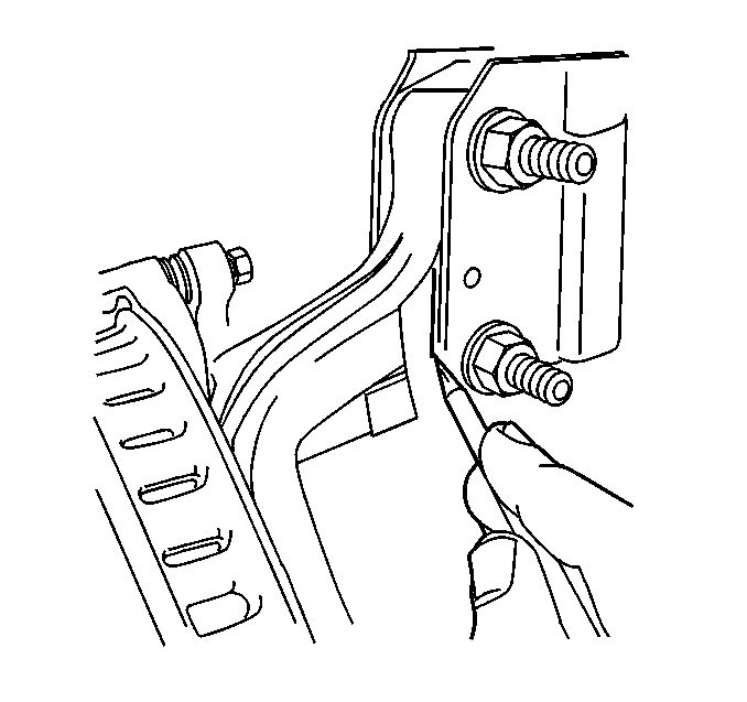
- Remove the bolt retaining the ABS harness bracket to the steering knuckle.
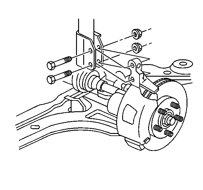
- Scribe the strut to the knuckle.
- Remove the bolts connecting the strut to the knuckle.
- Remove the knuckle from the vehicle.
Installation Procedure
- Install the knuckle to the vehicle.
- Install the bolts which connect the strut to the knuckle. Hand tighten only.
- Connect the front lower control arm ball stud to knuckle. Refer to Lower Control Arm Replacement .
- Attach the ABS bracket to the steering knuckle.
- Install the outer tie rod to the steering knuckle. Refer to Rack and Pinion Outer Tie Rod End Replacement .
- Install the front wheel drive shaft bearing. Refer to Front Wheel Bearing and Hub Replacement .
- Install the tire and wheel assembly. Refer to Tire and Wheel Removal and Installation .
- Lower the vehicle.
- Measure and adjust the front alignment. Refer to Front Camber Adjustment .
Notice: Refer to Fastener Notice in the Preface section.
Tighten
Tighten the ABS bracket bolt to 10 N·m (7 lb ft).
