Tools Required
J 42640 Steering Column Lock Pin
Removal Procedure
- Raise and support the vehicle. Refer to Lifting and Jacking the Vehicle in General Information.
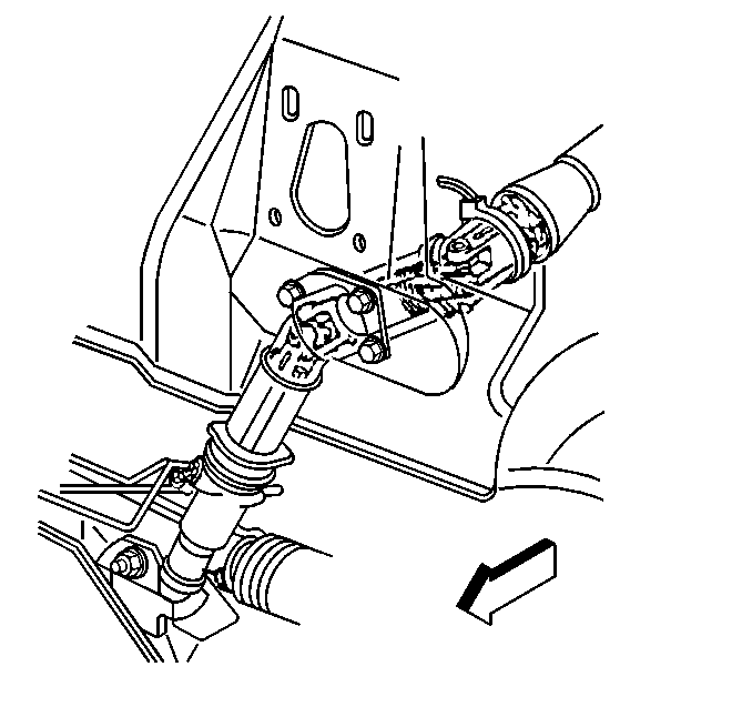
- Position the seal in order to provide access to the lower pinch bolt on the intermediate steering shaft.
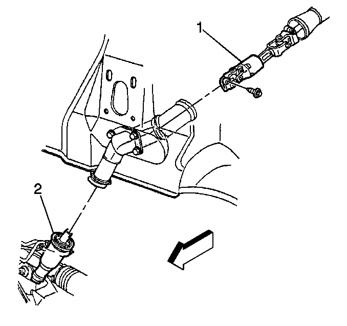
- Remove the lower pinch bolt from the power steering gear stub shaft (2).
- Insert J 42640 into the steering column access hole in order to lock the steering column. This will maintain the correct orientation.
- Remove the intermediate steering shaft (1) from the power steering gear stub shaft (2).
- Lower the vehicle.
- Remove the left instrument panel insulator. Refer to Instrument Panel Insulator Panel Replacement - Left Side in Instrument Panel, Gages and Console.
- Reposition the seal in order to gain access to the upper pinch bolt of the intermediate steering shaft.
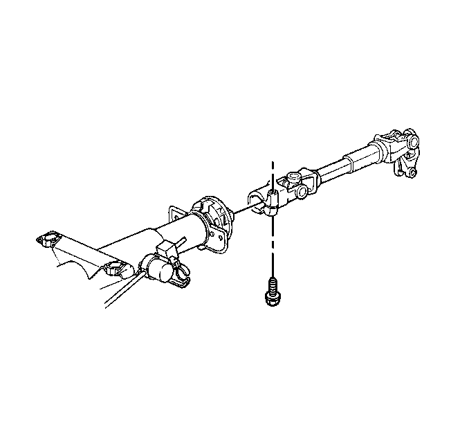
- Remove the upper pinch bolt from the intermediate steering shaft.
- Disconnect the intermediate steering shaft from the steering column.
- Remove the intermediate steering shaft from the vehicle.
Notice: The front wheels of the vehicle must be maintained in the straight ahead position and the steering column must be in the LOCK position before disconnecting the steering column or intermediate shaft. Failure to follow these procedures will cause improper alignment of some components during installation and result in damage to the SIR coil assembly.
Notice: The wheels of the vehicle must be straight ahead and the steering column in the LOCK position before disconnecting the steering column or intermediate shaft from the steering gear. Failure to do so will cause the SIR coil assembly to become uncentered, which may cause damage to the coil assembly.

Installation Procedure
- Position the intermediate steering shaft into place.
- Install the upper pinch bolt to the intermediate steering shaft at the steering column.
- Install the intermediate steering shaft seal onto the steering column.
- Install the left instrument panel insulator. Refer to Instrument Panel Insulator Panel Replacement - Left Side in Instrument Panel, Gages and Console.
- Raise and support the vehicle. Refer to Lifting and Jacking the Vehicle in General Information.
- Install the intermediate steering shaft (1) to the power steering gear stub shaft (2).
- Install the lower pinch bolt to the intermediate steering shaft at the power steering gear stub shaft.
- Install the intermediate steering shaft seal onto the power steering gear.
- Lower the vehicle.
Notice: Refer to Fastener Notice in the Preface section.
Tighten
Tighten the pinch bolt to 48 N·m (35 lb ft).
Tighten
Tighten the pinch bolt to 48 N·m (35 lb ft).
