CAMPAIGN: BRAKE S/LAMP SWITCH INSTALLATION & ADJUSTMENT

SUBJECT: BRAKE STOPLAMP SWITCH
MODELS AFFECTED: 1989 AND 1990 REGAL
The National Traffic and Motor Vehicle Safety Act, as amended, provides that each vehicle which is subject to a recall campaign of this type must be adequately repaired within a reasonable time after the owner has tendered it for repair. A failure to repair within sixty (60) days after tender of a vehicle is prima facie evidence of failure to repair within a reasonable time.
If the condition is not adequately repaired within a reasonable time, the owner may be entitled to an identical or reasonably equivalent vehicle at no charge or to a refund of the purchase price less a reasonable allowance for depreciation.
To avoid having to provide these burdensome solutions, every effort must be made to promptly schedule an appointment with each owner and to repair their vehicle as soon as possible. As you will see in reading the attached copy of the letter that is being sent to owners, the owners are being instructed to contact the Buick Customer Assistance Center if their dealer does not remedy the condition within five (5) days of the mutually agreed upon service date. If the condition is not remedied within a reasonable time, they are instructed on how to contact the National Highway Traffic Safety Administration.
DEFECT INVOLVED
General Motors has determined that a defect which relates to motor vehicle safety exists in certain 1989 and 1990 Buick Regal model vehicles. These vehicles may have a faulty brake stoplamp switch, which could result in the stoplamps not illuminating on application of the brakes. If this should occur in situations where a driver in a trailing vehicle is otherwise unable to recognize a braking action in sufficient time to respond appropriately, a vehicle crash could occur without prior warning. In some cases, failure of the stoplamp switch can result in the stoplamps staying on at all times.
In addition, in vehicles equipped with cruise control, a faulty stoplamp switch can result in resumption of the cruise control function upon release of the brake pedal. If this occurs, the cruise control feature can be disengaged by moving the cruise control switch to the "OFF" position, or by reapplying the brake. Once the vehicle speed drops below 12-14 MPH, the cruise feature will be automatically, disengaged. To prevent these conditions from occurring, an improved stoplamp switch will be installed on all involved vehicles.
VEHICLES INVOLVED
Involved are certain 1989 and 1990 Buick Regal model vehicles built within the following VIN breakpoints:
THROUGH AND YEAR MODEL PLANT FROM INCLUDING ---- ----- -------- -------- ----------- 1989 Regal Oshawa #2 K1445106 K1488782 1990 Regal Oshawa #2 L1400251 L1431378
Vehicles which Buick records indicate were previously repaired under warranty with Stoplamp Switch, Part Number 10180504, are not included in this campaign.
OWNER NOTIFICATION
Owners will be notified of this campaign on their vehicles by Buick Motor Division (see copy of owner letter included with this bulletin).
CHANGE OF OWNER INFORMATION
Dealers are to use the Dealer Communication System (DCS) to provide Buick Motor Division with subsequent Buick owner information. By reporting a change of owner name or address of a vehicle in campaign status over the DCS, the need to send a CVAR form for that vehicle is eliminated. Terminal input instructions are covered in the DCS Manual under Section 9, Page 9-J01A and B.
DEALER CAMPAIGN RESPONSIBILITY
Dealers are to service all vehicles subject to this campaign at no charge to owners, regardless of mileage, age of vehicle, or ownership, from this time forward.
Whenever a vehicle subject to this campaign is taken into your new or used vehicle inventory, or it is in your dealership for service in the future, you should take the steps necessary to be sure the campaign correction has been made before reselling or releasing the vehicle.
Owners of vehicles recently sold from your new vehicle inventory are to be contacted by the dealer, and arrangements made to make the required correction according to instructions contained in this bulletin.
DEALER MATERIAL
If your dealership has vehicles involved in this campaign, you will receive the following items:
o List of all vehicles involved in this campaign assigned to your dealership.
o One (1) Campaign Identification Label per vehicle involved.
Involved vehicles have been identified by Vehicle Identification Number Computer Listings. Computer listings contain the complete Vehicle Identification Number, owner name and address data, and are furnished to involved dealers with the campaign bulletin. Owner name and address data furnished will enable dealers to follow-up with owners involved in this campaign.
These listings may contain owner names and addresses obtained from State Motor Vehicle Registration Records. The use of such motor vehicle registration data for any other purpose is a violation of law in several states. Accordingly, you are urged to limit the use of this listing to the follow-up necessary to complete this campaign. Any dealer not receiving a computer listing with the campaign bulletin has no involved vehicles currently assigned.
REIMBURSEMENT
Customers with reimbursement claims should have their repair orders reviewed to determine if an improved design stoplamp switch (P/N 10180504) installed at the time of repair.
- If the part number on the repair order is P/N 10180504, no further action is required. Claim V6372 and reimburse customer under T1690.
- If the part number on the repair order is not P/N 10180504, an improved design stoplamp switch (P/N 10180504) must still be installed. Perform the campaign procedure outlined in this bulletin, claim V6371 for the replacement and reimburse the customer for the prior repair under T1690.
Customer requests for reimbursement of previous repairs to correct a stoplamp switch condition are to be submitted according to the instructions included with this bulletin. Owners must submit ORIGINAL DOCUMENTATION that reasonably confirms the amount of unreimbursed repair expense, a description of the repair, the date of the repair, and the person or entity performing the repair.
PARTS INFORMATION
Parts required to complete this campaign are to be obtained from General Motors Service Parts Operations (GMSPO). To ensure these parts will be obtained as soon as possible, they should be ordered from GMSPO on a "C.I.O." order with no special instruction code, but on an advise code (2).
Quantity/ Part Number Description Vehicle ----------- ------------------------ --------- 10180504 Stoplamp Switch Assembly 1
GMSPO will preship each dealer five (5) stoplamp switch assemblies. These parts will be billed on the dealer parts account.
SERVICE PROCEDURE
NOTICE: ALL DEALERS ARE BEING SENT AN INSTRUCTIONAL VIDEO TAPE ON THE STOPLAMP SWITCH SETTING PROCEDURE. PLEASE BE SURE TO VIEW THIS VIDEO TAPE BEFORE PERFORMING THE PROCEDURE BELOW. FLEET WARRANTY STATIONS INTENDING TO PERFORM THIS CAMPAIGN MAY OBTAIN THIS VIDEO TAPE BY CALLING (313) 525-8200 BEFORE DECEMBER 14, 1990 AND ASK FOR HANK BOLSEN.
STOPLAMP SWITCH REMOVAL AND INSTALLATION
1. Remove air cleaner assembly and disconnect negative battery cable.
2. Remove left side insulator panel and slide steering shaft protective sleeve towards the cowl.
3. Remove air distribution tube and pull down.
4. Remove retainer clip holding stoplamp switch to column bracket.
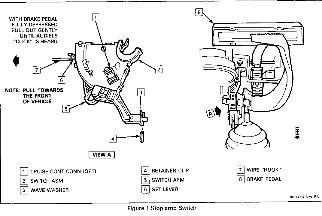
5. Disconnect switch arm from pedal by pushing arm over and off brake pedal pin. Release switch by pulling down and releasing top snap clip.
6. Disconnect connector position assurance (CPA) locking pins from four wire and two wire electrical connectors. (Two wire connector not present on vehicles without cruise control feature).
7. Disconnect four wire and two wire connectors.
8. Remove brake stoplamp switch assembly.
9. If vehicle is equipped with cruise control, connect two wire connector and CPA locking pin to new switch assembly.
10. Install new switch assembly by pushing switch up until seated into top snap clip. Do not attach switch arm to pin on brake pedal at this time.
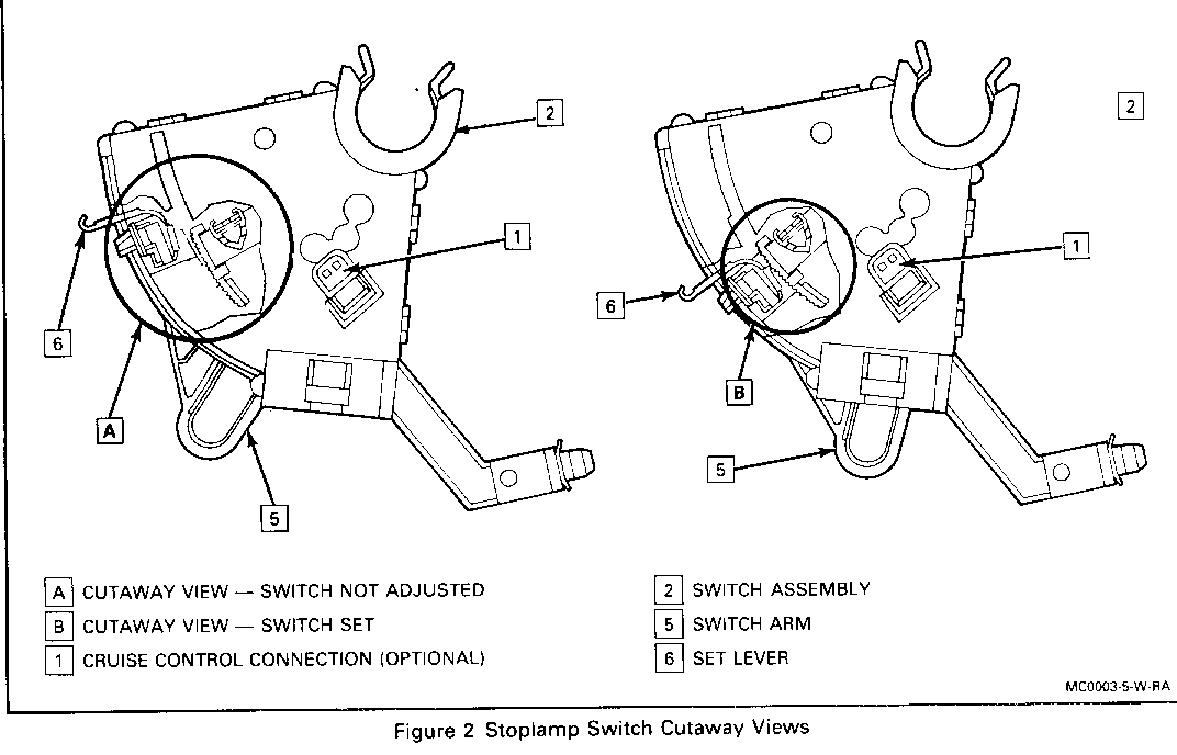
NOTICE: Make sure brake switch is not adjusted (metal clip on actuator is not engaged with the serrations on the bottom of the carrier) as shown in Figure 2.
11. Install retainer clip which holds switch to steering column bracket.
12. Push brake pedal down to floor pan and install switch arm over and onto brake pedal pin.
13. Pull brake pedal all the way rearward and listen for switch to ratchet to set position. At least three (3) clicks of the ratchet must be heard.
14. Connect four wire connector and CPA locking pin.
15. Position steering shaft protective sleeve.
16. Reconnect negative battery cable.
17. Inspect stoplamp switch operation. If stoplamps do not operate, refer to the "STOPLAMP SWITCH ADJUSTMENT" section of this bulletin. If stoplamps do operate, continue through step 23.
18. Check setting of cruise vacuum dump, if so equipped. With brake pedal at rest, make sure the plunger is fully seated into the barrel. If it is not fully seated, push the dump valve forward until the plunger is inside the barrel and then pull rearward on brake pedal to properly set the valve. If the plunger is already fully seated into the barrel, the vacuum dump valve is already properly set and no further adjustment is required.
19. Reconnect air distribution tube.
20. Reinstall left side sound insulator panel.
21. Reinstall air cleaner assembly.
22. Vehicles equipped with 2.8L and 3.1L engines must have the following procedure performed to "relearn" the idle. This function was lost from the ECM's memory due to the loss of battery power.
a. Place air conditioning controls in "OFF" position.
b. Firmly apply parking brake and block drive wheels. Start engine and shift transaxle into "DRIVE".
c. Allow engine to run a maximum of 10 minutes or until the engine cooling fan has cycled once, whichever occurs first.
d. Shift transaxle to "PARK", then turn the ignition key to the "OFF" position for at least 5 seconds.
e. Repeat step (b).
f. Allow engine to run for at least 5 minutes.
23. Install Campaign Identification Label.
STOPLAMP SWITCH ADJUSTMENT
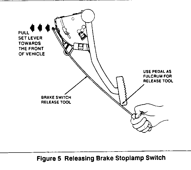
(Figures 1 through 5 may be helpful in performing this procedure).
1. Depress brake pedal as far as possible and hold.
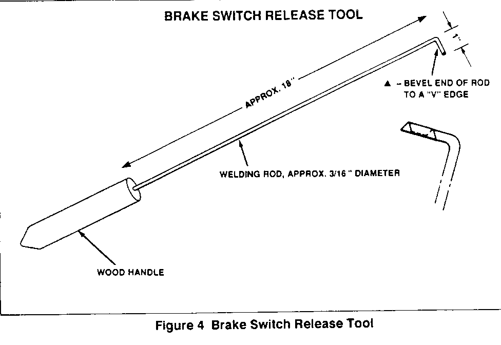
2. Using a stiff wire and a hooked end (see Figures 4 and 5), gently pull switch set lever forward (toward front of vehicle), and listen for an audible click indicating release of automatic adjustor.
NOTICE: If no click is heard, release brake pedal and repeat above procedure.
3. After release of automatic adjustor, pull brake pedal all the way rearward. Listen for switch to ratchet into set position (setting the stoplamp switch). At least three (3) clicks of the ratchet must be heard.
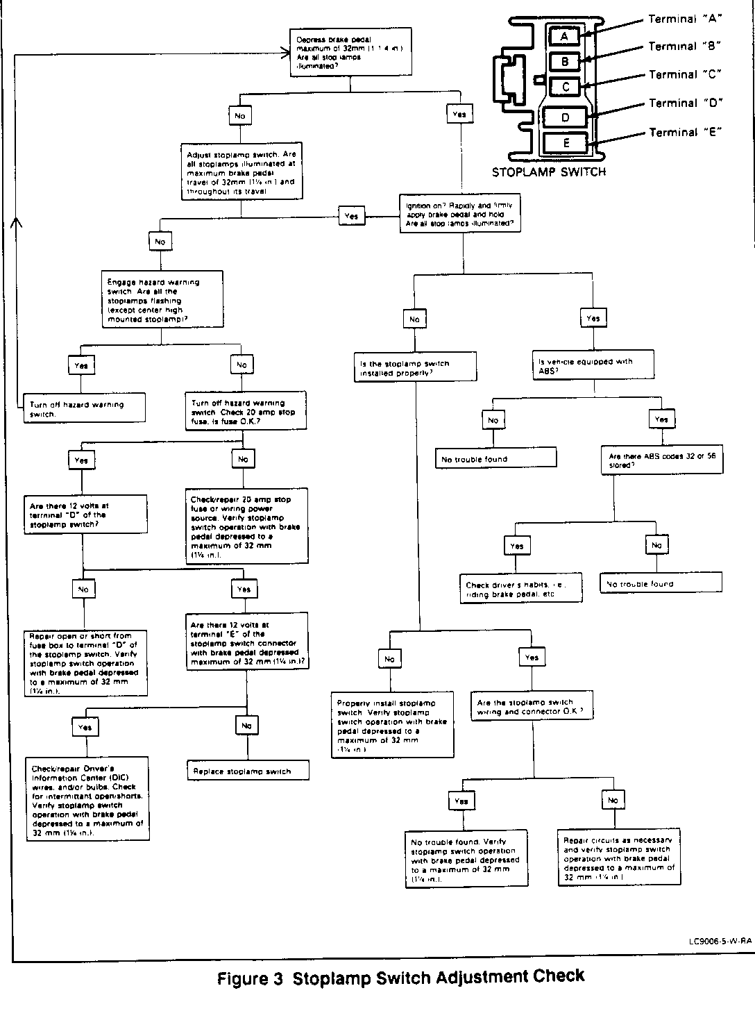
4. Inspect operation of stoplamps. Stoplamps should operate at maximum brake pedal travel of 25mm (I in.) and throughout the remainder of its travel. If stoplamps do not operate properly, repeat switch adjustment procedure one more time. If switch still fails to operate properly, refer to the "STOPLAMP SWITCH ADJUSTMENT CHECK" chart (see Figure 3).
If stoplamps do operate properly, return to step 17 of the "STOPLAMP SWITCH REMOVAL AND INSTALLATION" procedure above.
CAMPAIGN IDENTIFICATION LABEL
Each vehicle corrected in accordance with the instructions outlined in this Product Campaign Bulletin will require a "Campaign Identification Label." Each label provides a space to include the five (5) digit dealer code of the dealer performing the campaign service. This information may be inserted with a typewriter or a ball point pen.
Each "Campaign Identification Label" is to be located on the radiator core support in an area which will be visible when the vehicle is brought in for periodic servicing by the owner. Apply "Campaign Identification Label" only on a clean, dry surface.
DISPOSITION OF PARTS
Replaced parts must be held for disposition by Buick Zone or Branch contact personnel. Parts must have a claim tag attached showing the repair order and the VIN of the vehicle from which they were removed.
WARRANTY INFORMATION
Use the "T" labor operation for reimbursement for previous customer paid repair. The Product Campaign must still be performed and the appropriate labor operation used. DLR. PART FAILED PARTS FAILURE LABOR LABOR OTHER MTL OPER. COUNT PART NO. ALLOW. CODE OP NO HOURS HOURS TWG
o Install and Adjust Stoplamp Switch 1 10180504 96 V6371 0.8 0.1* --
o Review Repair Order, 10180504 Switch already installed -- -- -- 96 V6372*** 0.2 0.1* --
o Reimbursement for previously customer paid stoplamp switch repair. -- -- -- 96 T1690 (See Instructions for reimbursement)
* Dealer Administration Allowance ** List current dealer price, plus 30% *** V6372 operation to be used only with T1690 operation when part number 10180504 has been previously installed
REQUEST FOR REIMBURSEMENT INSTRUCTIONS
1. Customer presents dealer with original paid receipts covering repairs.
2. Dealer completes a Repair Order (R.O.) showing the following: -Repair order date -Vehicle Identification Number -Current mileage -Owner's address -Attaches original owner's or dealer's paid invoices/receipts covering repair -Use Labor Operation Number T1690 and Failure Code 96 -Enters total of reimbursement based on 100% of OWNERS EXPENSE
3. Owner signs the repair order as acknowledgement of requested reimbursement amount.
4. Owner is given a copy of repair order.
5. Dealer assigns a Warranty Management System (WMS) authorization code to the claim and enters it on the WMS Authorization Log.
6. The dealer submits a claim to Buick for processing.
7. Dealer issues the owner a reimbursement check for the approved amount. The check number must be entered on the repair order and a copy of the check must be attached to original paid invoices/receipts.
8. All supporting documentation must be available for review by Buick personnel as needed.
NOTICE: REFER TO BUICK SERVICE POLICIES AND PROCEDURES MANUAL, SECTION 1.6.1 1 FOR SPECIFIC PROCEDURES FOR CUSTOMER REIMBURSEMENT VERIFICATION.
IN THE EVENT THE DEALER SERVICE MANAGER AND THE OWNER CANNOT REACH AGREEMENT ON AMOUNT ELIGIBLE FOR REIMBURSEMENT AFTER REVIEW OF INVOICES/RECEIPTS, THE ZONE/BRANCH SHOULD BE CONTACTED FOR DETERMINATION OF COVERED EXPENSES. IN SUCH CASES, AN EXPLANATION SHOULD BE INCLUDED ON THE R.O.
Dear Buick Owner:
This notice is sent to you in accordance with the requirements of the National Traffic and Motor Vehicle Safety Act.
REASON FOR THIS RECALL
General Motors has determined that a defect which relates to motor vehicle safety exists in certain 1989 and 1990 Buick Regal model vehicles. These vehicles may have a faulty brake stoplamp switch, which could result in the stoplamps not illuminating on application of the brakes. If this should occur in situations where a driver in a trailing vehicle is otherwise unable to recognize a braking action in sufficient time to respond appropriately, a vehicle crash could occur without prior warning. In some cases, failure of the stoplamp switch can result in the stoplamps staying on at all times.
In addition, in vehicles equipped with cruise control, a faulty stoplamp switch can result in resumption of the cruise control function upon release of the brake pedal. If this occurs, the cruise control feature can be disengaged by moving the cruise control switch to the "OFF" position, or by reapplying the brake. Once the vehicle speed drops below 12-14 MPH, the cruise feature will be automatically, disengaged.
WHAT WE WILL DO
To prevent these conditions from occurring, an improved design stoplamp switch will be installed on your vehicle. This service will be performed for you at no charge.
WHAT YOU SHOULD DO
Please contact your Buick dealer as soon as possible to arrange a service date. Instructions for making this correction have been sent to your dealer and parts are available. The labor time necessary to perform this service correction is approximately fifty (50) minutes. Please ask your dealer if you wish to know how much additional time will be needed to schedule and process your vehicle.
If you have already experienced this condition and paid for all or part of the repair, you may request reimbursement through your Buick dealer. When doing so, you should present the dealer with documentation which reasonably confirms the amount of unreimbursed repair expense, the date of repair and the person or entity performing the repair.
When you make your reimbursement request, your repair order will be reviewed to assure that an improved design stoplamp switch was installed. If another switch was used for the repair, it will need to be replaced and a service date to perform this campaign should be scheduled. If the improved design part was installed, your vehicle already has the required part and no further action is necessary. In either case, a claim for reimbursement of the prior repair may be filed.
Your Buick dealer is best equipped to obtain parts and provide service to ensure that your vehicle is corrected as promptly as possible. If, however, you take your vehicle to your dealer on the agreed service date, and they do not remedy this condition on that date or within five (5) days, we recommend you contact the Buick Customer Assistance Center by calling 1-800-521-7300.
After contacting your dealer and the Customer Assistance Center, if you are still not satisfied that we have done our best to remedy this condition without charge and within a reasonable time, you may wish to write the Administrator, National Highway Traffic Safety Administration, 400 Seventh Street, S. W., Washington, D.C. 20590 or call 1-800-424-9393 (Washington D.C. residents use 366-0123).
The enclosed owner reply card identifies your vehicle. Presentation of this card to your dealer will assist in making the necessary correction in the shortest possible time. If you have sold or traded your vehicle, please let us know by completing the postage paid reply card and returning it to us.
We are sorry to cause you this inconvenience; however, we have taken this action in the interest of your safety and continued satisfaction with our products.

General Motors bulletins are intended for use by professional technicians, not a "do-it-yourselfer". They are written to inform those technicians of conditions that may occur on some vehicles, or to provide information that could assist in the proper service of a vehicle. Properly trained technicians have the equipment, tools, safety instructions and know-how to do a job properly and safely. If a condition is described, do not assume that the bulletin applies to your vehicle, or that your vehicle will have that condition. See a General Motors dealer servicing your brand of General Motors vehicle for information on whether your vehicle may benefit from the information.
