GM Service Manual Online
For 1990-2009 cars only

Tools Required

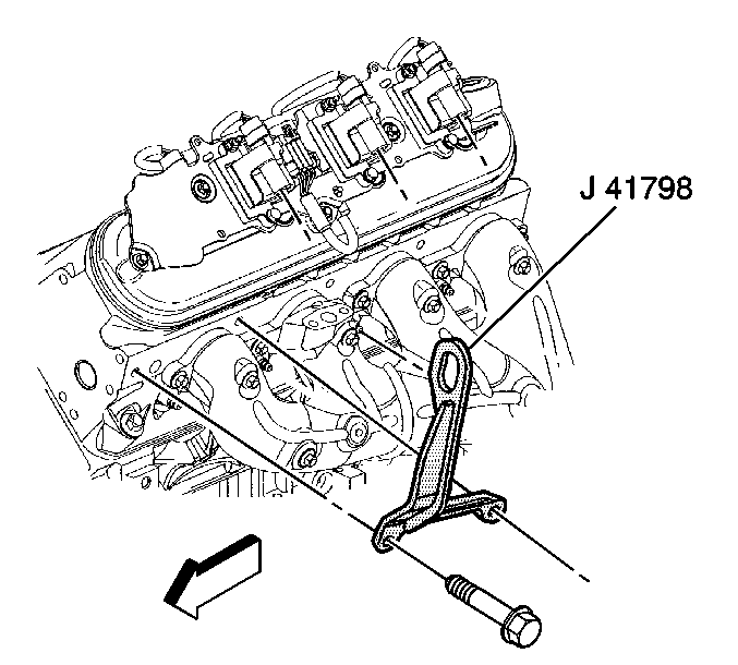
    • J 41798 Engine Lift Bracket
    • J 21366 Converter Holding Strap
    • J 38185 Hose Clamp Pliers

Removal Procedure


    Object Number: 898333  Size: SH
  1. Remove the hood. Refer to Hood Replacement .
  2. Disconnect the negative battery cable. Refer to Battery Negative Cable Disconnection and Connection .
  3. Remove the intake manifold sight shield. Refer to Upper Intake Manifold Sight Shield Replacement .
  4. Recover the refrigerant. Refer to Refrigerant Recovery and Recharging .
  5. Remove the radiator. Refer to Radiator Replacement .
  6. Remove the radiator support brace. Refer to Radiator Support Diagonal Brace Replacement .
  7. Remove the front differential drive axle, if equipped with 4-wheel drive (4WD). Refer to Differential Carrier Assembly Replacement .
  8. Remove the wheel drive shafts, if equipped with 4-wheel drive. Refer to Wheel Drive Shaft Replacement .
  9. Remove the intake manifold. Refer to Intake Manifold Replacement .
  10. Disconnect the following electrical connectors:
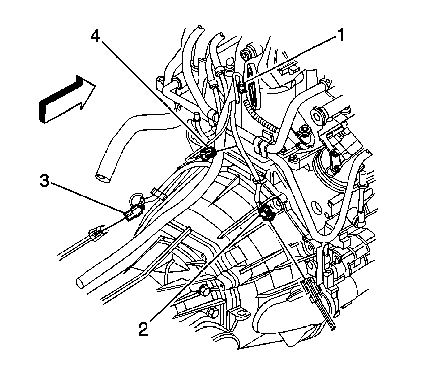
  11. • Oil pressure sensor (1)
    • Oxygen sensors (2, 3)
    • Camshaft position (CMP) sensor (4)

    Object Number: 871567  Size: SH
  12. Remove the air conditioning (A/C) compressor hose. Refer to Compressor Hose Assembly Replacement .
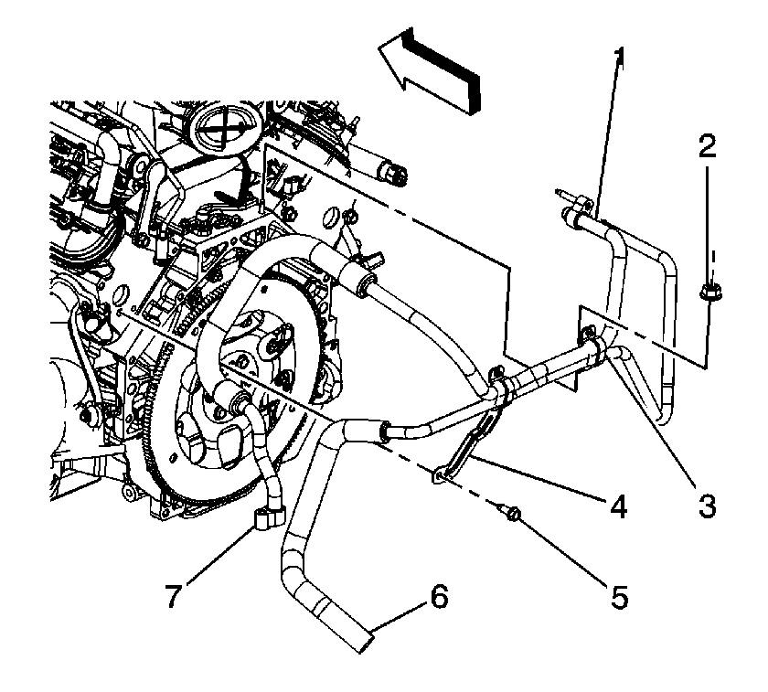
  13. Disconnect the rear auxiliary A/C compressor pipe fitting (7).
  14. Remove the rear auxiliary A/C compressor pipe nut and bolt (2, 5).
  15. Tie the pipe assembly out of the way.

  16. Object Number: 898343  Size: SH
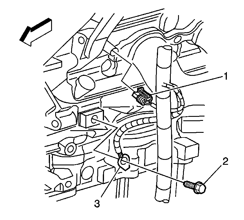
  17. Disconnect the engine coolant temperature (ECT) sensor (1).
  18. Remove the ground terminal bolt (2).
  19. Remove the retaining clips from the brackets.

  20. Object Number: 898468  Size: SH
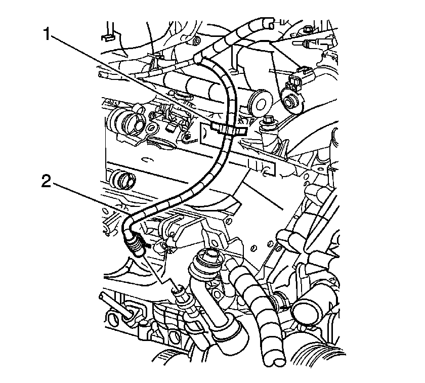
  21. Disconnect the A/C pressure switch electrical connector (2).
  22. Remove the retaining clip (1) from the cylinder head.
  23. Raise and suitably support the vehicle. Refer to Lifting and Jacking the Vehicle .

  24. Object Number: 898338  Size: SH
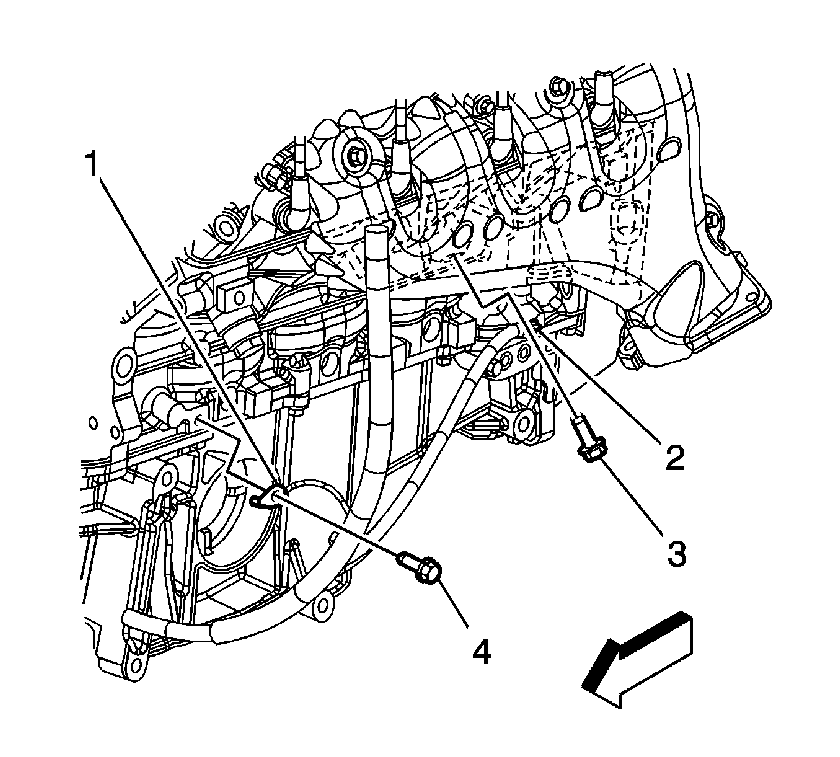
  25. Remove the ground terminal bolts (2, 4).
  26. Remove the starter. Refer to Starter Motor Replacement .

  27. Object Number: 899616  Size: SH
  28. Remove the battery cable channel bolt.
  29. Remove the battery cable channel from the oil pan.

  30. Object Number: 898469  Size: SH
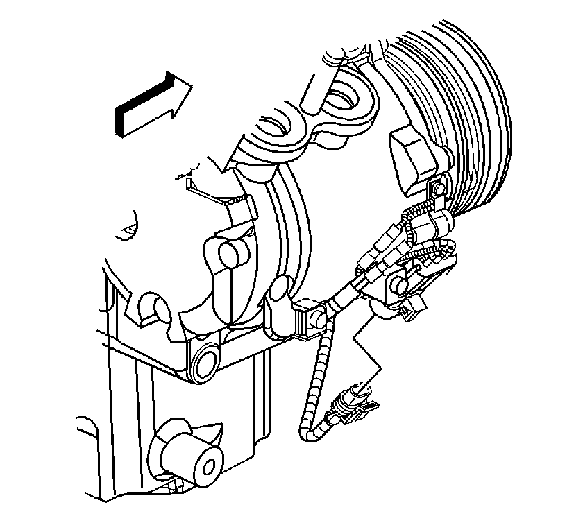
  31. Disconnect the A/C compressor electrical connector.
  32. Lower the vehicle.
  33. Gather all branches of the engine wiring harness and reposition the harness off to the side.

  34. Object Number: 395686  Size: SH
  35. Remove the generator cable from the generator. Perform the following:
  36. 28.1. Slide the boot down revealing the terminal stud.
    28.2. Remove the generator cable nut from the terminal stud.
    28.3. Remove the generator cable.

    Object Number: 310813  Size: SH
  37. Remove the generator bracket bolts.
  38. Position the bracket with generator aside.

  39. Object Number: 901490  Size: SH
  40. Using the J 38185 , remove the inlet hose from the water outlet.

  41. Object Number: 901491  Size: SH
  42. Using the J 38185 , remove the outlet hose from the water outlet.

  43. Object Number: 901493  Size: SH
  44. Disconnect the auxiliary heater inlet and outlet hose/pipe assembly from the heater water shutoff valve pipes.

  45. Object Number: 901492  Size: SH
  46. Using the J 38185 , remove the auxiliary heater inlet and outlet hoses/pipes from the water pump

  47. Object Number: 309151  Size: SH
  48. Remove the ignition coils as required for the proper fit of J 41798 . Refer to Ignition Coil Replacement .
  49. Notice: Refer to Fastener Notice in the Preface section.

  50. Install J 41798 .
  51. Tighten

        • Tighten the M8 bolts to 25 N·m (18 lb ft).
        • Tighten the M10 bolts to 50 N·m (37 lb ft).
  52. Raise the vehicle.
  53. Remove the catalytic converter. Refer to Catalytic Converter Replacement .

  54. Object Number: 876704  Size: SH
  55. Remove the 3 bracket bolts from both the right and the left sides of the frame engine mount .

  56. Object Number: 9096  Size: SH
  57. Remove the torque converter bolts.

  58. Object Number: 396797  Size: SH
  59. Remove the transmission oil level indicator tube nut.

  60. Object Number: 396798  Size: SH
  61. Remove the transmission oil level indicator tube.

  62. Object Number: 859004  Size: SH
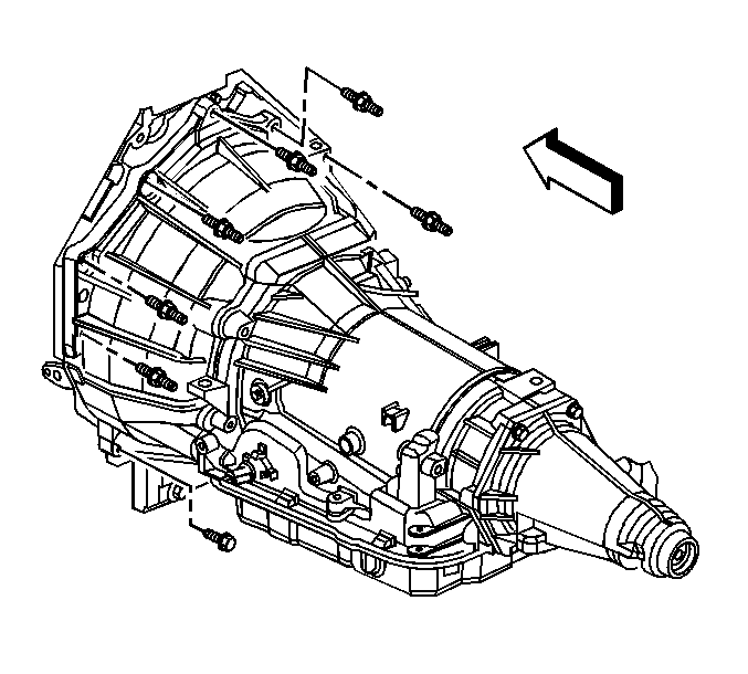
  63. Remove the transmission bolt and stud on the right side.

  64. Object Number: 859003  Size: SH
  65. Remove the lower transmission bolt/studs.
  66. Lower the vehicle.
  67. Remove the 3 upper transmission bolts/studs.
  68. Install an engine hoist to the J 41798 .
  69. Install a floor jack under the transmission for support.
  70. Separate the engine from the transmission.
  71. Remove the engine.
  72. Install the engine to an engine stand.
  73. Install the J 21366 .

Installation Procedure


    Object Number: 859003  Size: SH
  1. Remove the J 21366 .
  2. Install an engine hoist to the J 41798 .
  3. Remove the engine from the engine stand.
  4. Install the engine.
  5. Mate the engine to the transmission.
  6. Remove the floor jack from under the transmission for support.
  7. Notice: Refer to Fastener Notice in the Preface section.

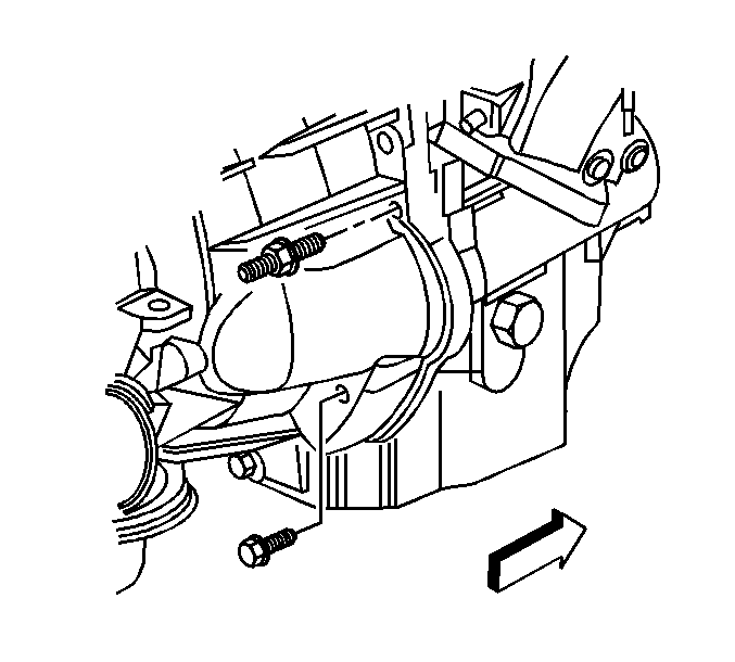
  8. Install the 3 upper transmission bolts/studs.
  9. Tighten
    Tighten the bolts/studs to 50 N·m (37 lb ft).
  10. Raise the vehicle.
  11. Install the lower transmission bolt/studs.
  12. Tighten
    Tighten the bolts/studs to 50 N·m (37 lb ft).

    Object Number: 859004  Size: SH
  13. Install the transmission bolt and stud on the right side.
  14. Tighten
    Tighten the bolts/studs to 50 N·m (37 lb ft).


    Object Number: 396798  Size: SH
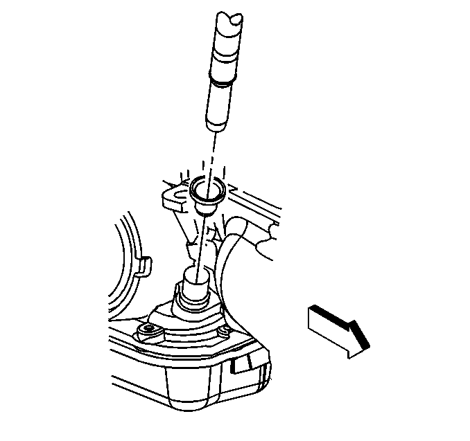
  15. Install the transmission oil level indicator tube.
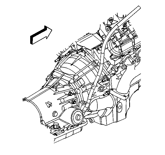
  16. Object Number: 396797  Size: SH
  17. Install the transmission oil level indicator tube nut.
  18. Tighten
    Tighten the nut to 10 N·m (89 lb ft).

    Object Number: 9096  Size: SH
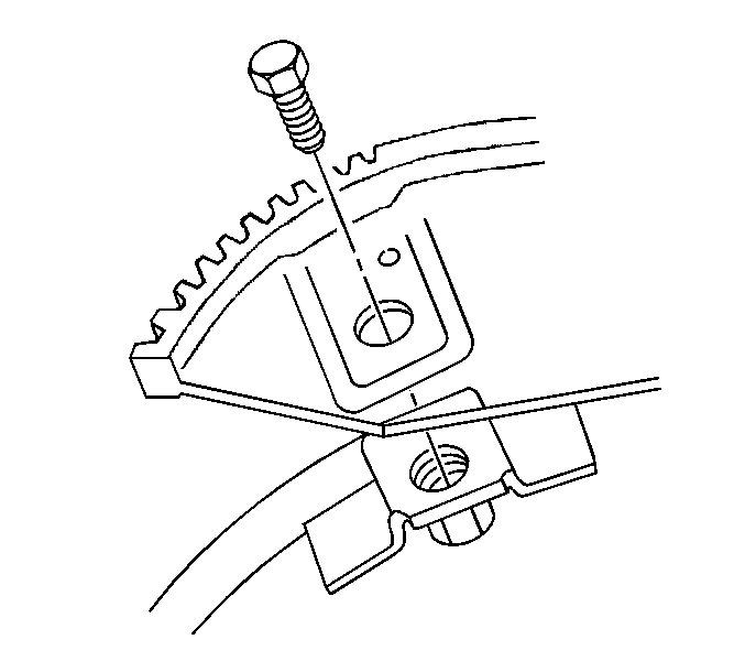
  19. Install the torque converter bolts.
  20. Tighten
    Tighten the bolts to 60 N·m (44 lb ft).
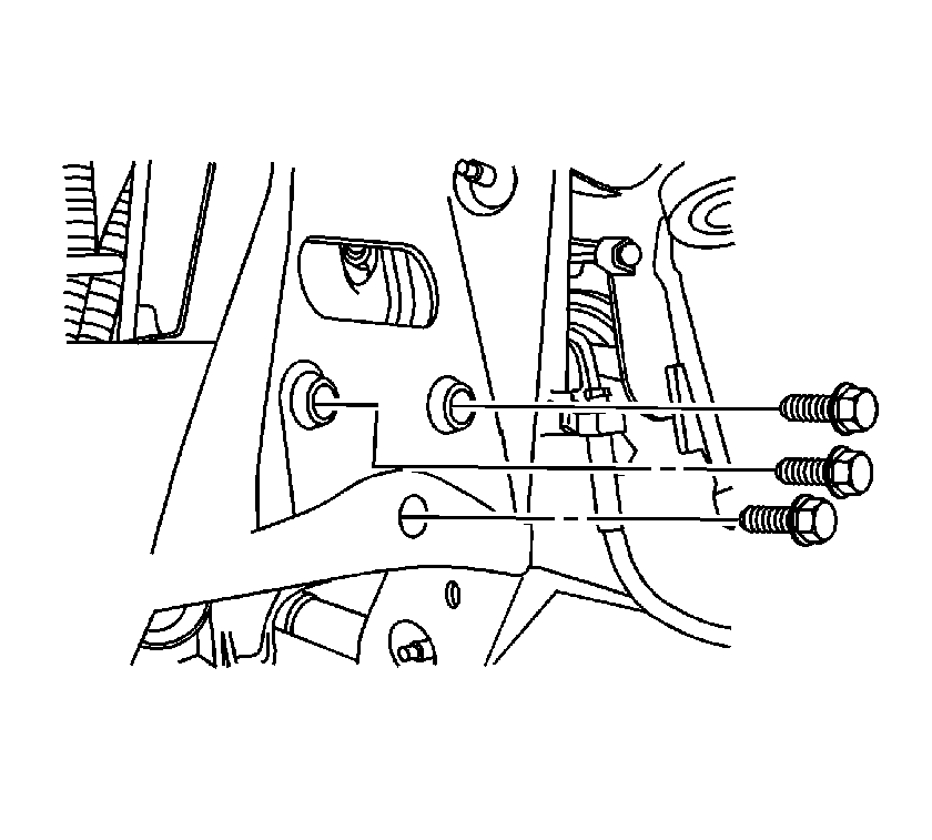

    Object Number: 876704  Size: SH
  21. Install the 3 bracket bolts to both the right and the left sides of the frame engine mount.
  22. Tighten
    Tighten the bolts to 50 N·m (37 lb ft).

  23. Install the catalytic converter. Refer to Catalytic Converter Replacement .
  24. Lower the vehicle.

  25. Object Number: 309151  Size: SH
  26. Remove J 41798 .
  27. Install the ignition coils, as required. Refer to Ignition Coil Replacement .
  28. Tighten
    Tighten the bolts to 8 N·m (71 lb in).
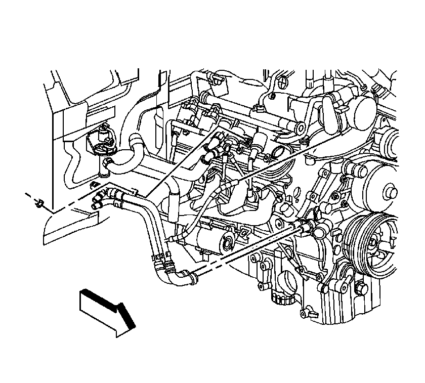

    Object Number: 901492  Size: SH
  29. Install the auxiliary heater inlet and outlet hoses/pipes to the water pump using the J 38185 .
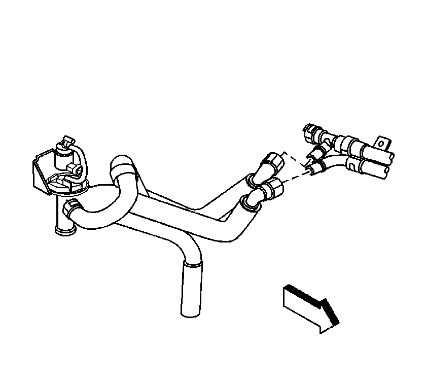
  30. Object Number: 901493  Size: SH
  31. Connect the auxiliary heater inlet and outlet hose/pipe assembly to the heater water shutoff valve pipes.
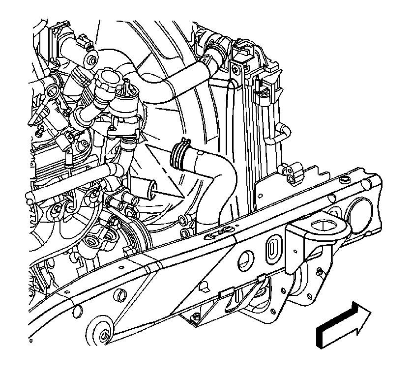
  32. Object Number: 901491  Size: SH
  33. Install the outlet hose to the water outlet using the J 38185 .
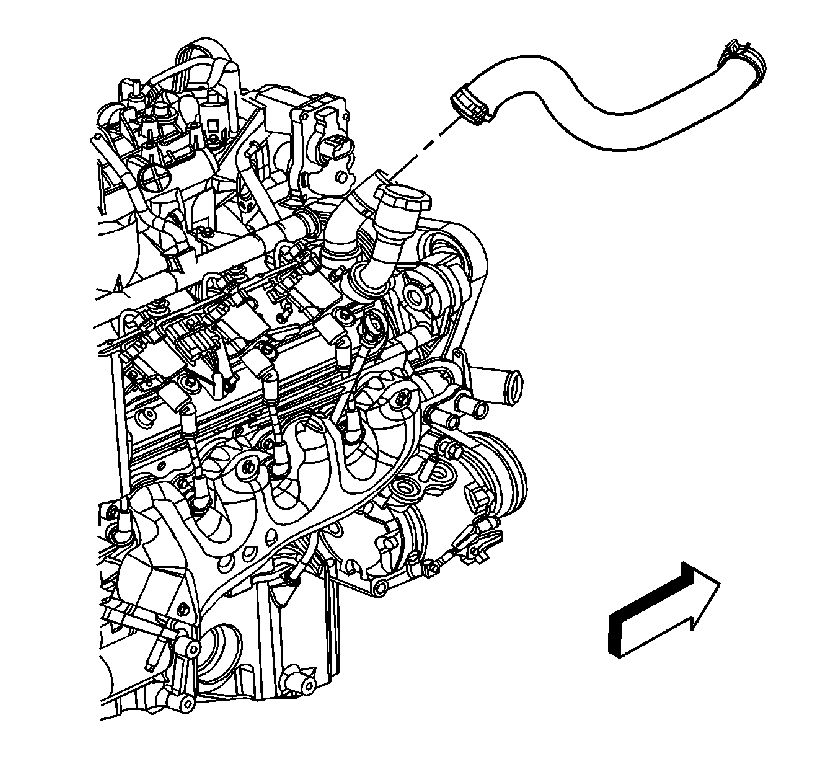
  34. Object Number: 901490  Size: SH
  35. Install the inlet hose to the water outlet using the J 38185 .
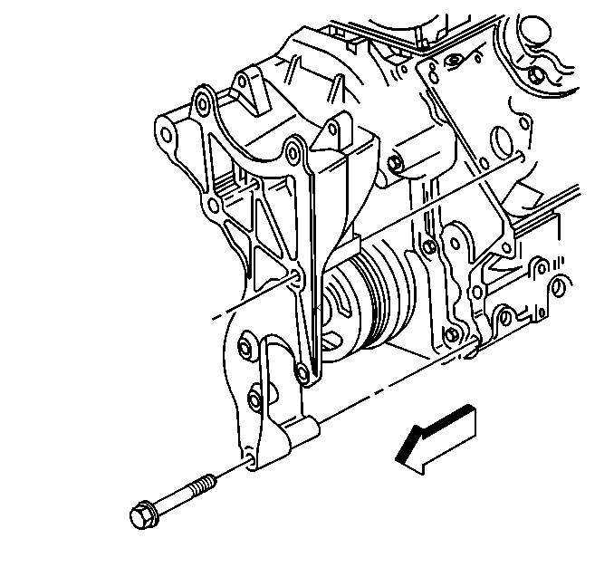
  36. Object Number: 310813  Size: SH
  37. Position the bracket with generator to the engine.
  38. Install the generator bracket bolts.
  39. Tighten
    Tighten the bolts to 50 N·m (37 lb ft).
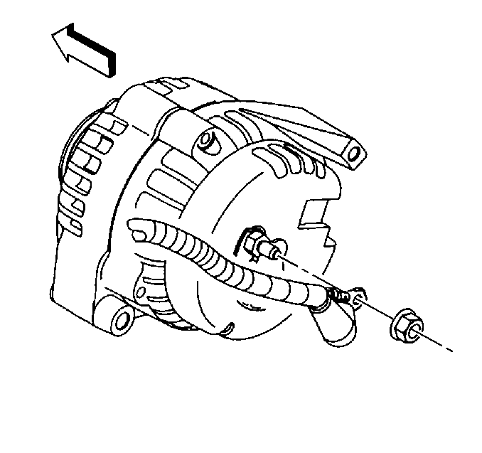

    Object Number: 395686  Size: SH
  40. Install the generator cable to the generator, perform the following procedure:
  41. 25.1. Install the generator cable.
    25.2. Install the generator cable nut to the terminal stud.

    Tighten
    Tighten the nut to 9 N·m (80 lb in).

    25.3. Slide the boot down covering the terminal stud.

    Object Number: 898469  Size: SH
  42. Gather all branches of the engine wiring harness and position the harness over the engine.
  43. Raise the vehicle.
  44. Connect the A/C compressor electrical connector.
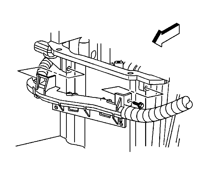
  45. Object Number: 899616  Size: SH
  46. Install the battery cable channel to the oil pan.
  47. Install the battery cable channel bolt.
  48. Tighten
    Tighten the bolt to 12 N·m (106 lb in).

    Object Number: 898338  Size: SH
  49. Install the starter. Refer to Starter Motor Replacement .
  50. Install the ground terminal bolts (2, 4).
  51. Tighten
    Tighten the bolt to 25 N·m (18 lb ft).

  52. Lower the vehicle.

  53. Object Number: 898468  Size: SH
  54. Install the retaining clip (1) to the cylinder head.
  55. Connect the A/C pressure switch electrical connector (2).
  56. Object Number: 898343  Size: SH
  57. Install the retaining clips to the brackets.
  58. Install the ground terminal bolt (2).
  59. Tighten
    Tighten the bolt to 25 N·m (18 lb ft).

  60. Connect the ECT sensor (1).

  61. Object Number: 871567  Size: SH
  62. Install the rear auxiliary A/C compressor pipe nut and bolt (2, 5).
  63. Tighten
    Tighten the nut/bolt to 20 N·m (15 lb ft).

  64. Connect the rear auxiliary A/C compressor pipe fitting (7).
  65. Tighten
    Tighten the nut to 16 N·m (12 lb ft).

  66. Install the A/C compressor hose. Refer to Compressor Hose Assembly Replacement .
  67. Object Number: 898333  Size: SH
  68. Connect the following electrical connectors:
  69. • Oil pressure sensor (1)
    • Oxygen sensors (2, 3)
    • Camshaft position (CMP) sensor (4)
  70. Install the intake manifold. Refer to Intake Manifold Replacement .
  71. Install the wheel drive shafts. Refer to Wheel Drive Shaft Replacement .
  72. Install the front differential drive axle, if equipped with 4WD. Refer to Differential Carrier Assembly Replacement .
  73. Install the radiator support brace. Refer to Radiator Support Diagonal Brace Replacement .
  74. Install the radiator. Refer to Radiator Replacement .
  75. Recharge the refrigerant. Refer to Refrigerant Recovery and Recharging .
  76. Connect the negative battery cable. Refer to Battery Negative Cable Disconnection and Connection .
  77. Prelube the engine. Refer to Engine Prelubing .
  78. Perform the CKP system variation learn procedure. Refer to Crankshaft Position System Variation Learn .
  79. Install the hood. Refer to Hood Replacement .
  80. Important: After an overhaul, the engine should be tested. Use the following procedure after the engine is installed in the vehicle.
  81. Test the vehicle using the following procedure:
  82. 53.1. Disable the ignition system.
    53.2. Crank the engine several times. Listen for any unusual noises or evidence that parts are binding.
    53.3. Enable the ignition system.
    53.4. Start the engine and listen for unusual noises.
    53.5. Check the vehicle oil pressure gauge or light and confirm that the engine has acceptable oil pressure.
    53.6. Run the engine speed at about 1,000 RPM until the engine has reached normal operating temperature.
    53.7. Inspect for fuel, oil and/or coolant leaks while the engine is running.
  83. Install the intake manifold sight shield. Refer to Upper Intake Manifold Sight Shield Replacement .