GM Service Manual Online
For 1990-2009 cars only
Figure 1:

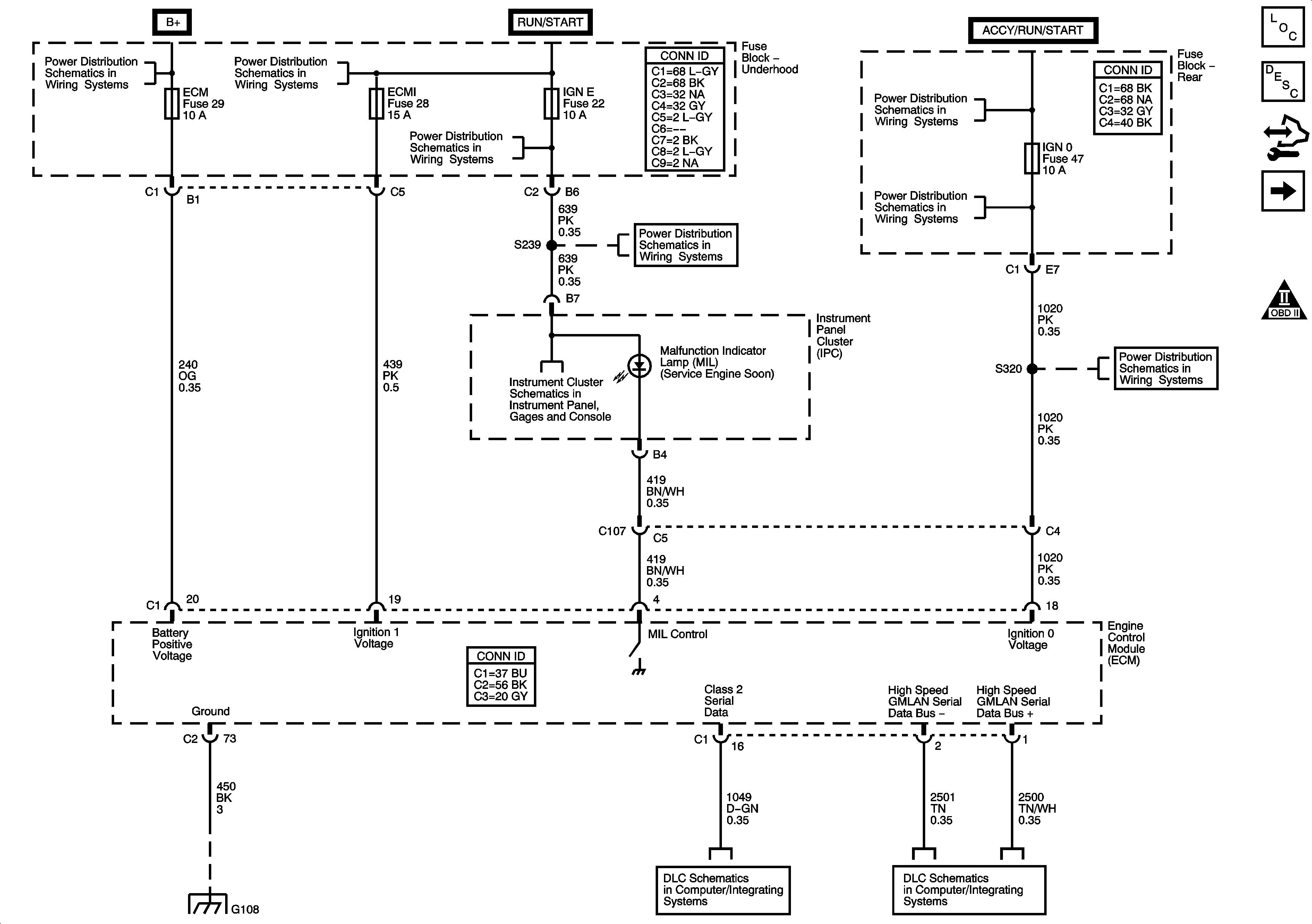
Module Power, Ground, Serial Data, and MIL

Object Number: 1594038  Size: FS
Master Electrical Component List
Engine Control Module Description
Control Module References
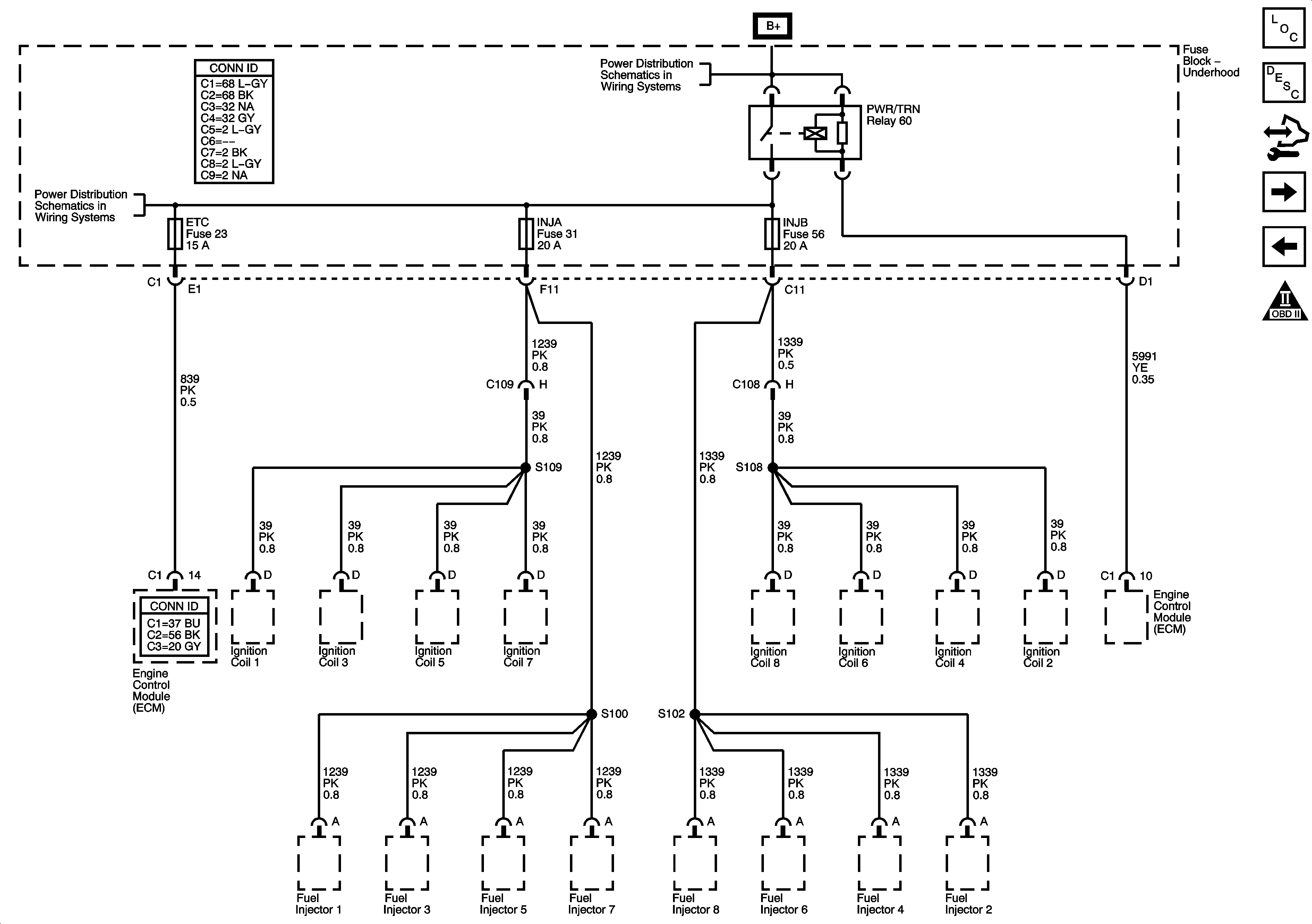
Underhood Fuse Block - PWR/TRN Relay - 1 of 2
Engine Controls Schematic Icons
Underhood Fuse Block
ACCY/RUN, RUN/START, Bus Bars, and IGN B Fuse
BCK/UP, BTSI, IGN E, TBC IGN1, and TRLR BCK/UP Fuses
Power, Ground, Serial Data, and MIL
BCK/UP, BTSI, IGN E, TBC IGN1, and TRLR BCK/UP Fuses
Ignition Switch - ACCY/RUN/START, RUN, and START Bus Bars, IGN A and CRNK Fuses
FRT WPR, IGN 0, RAIN, TBC ACC, TBC IG, and TCM Fuses
G108
SP205
Power, Ground, Data Link Connector
Figure 2:

Underhood Fuse Block - PWR/TRN Relay - 1 of 2


Object Number: 1594039  Size: FS
Master Electrical Component List
Engine Control Module Description
Control Module References
Underhood Fuse Block - PWR/TRN Relay - 2 of 2
Module Power, Ground, Serial Data, and MIL
Engine Controls Schematic Icons
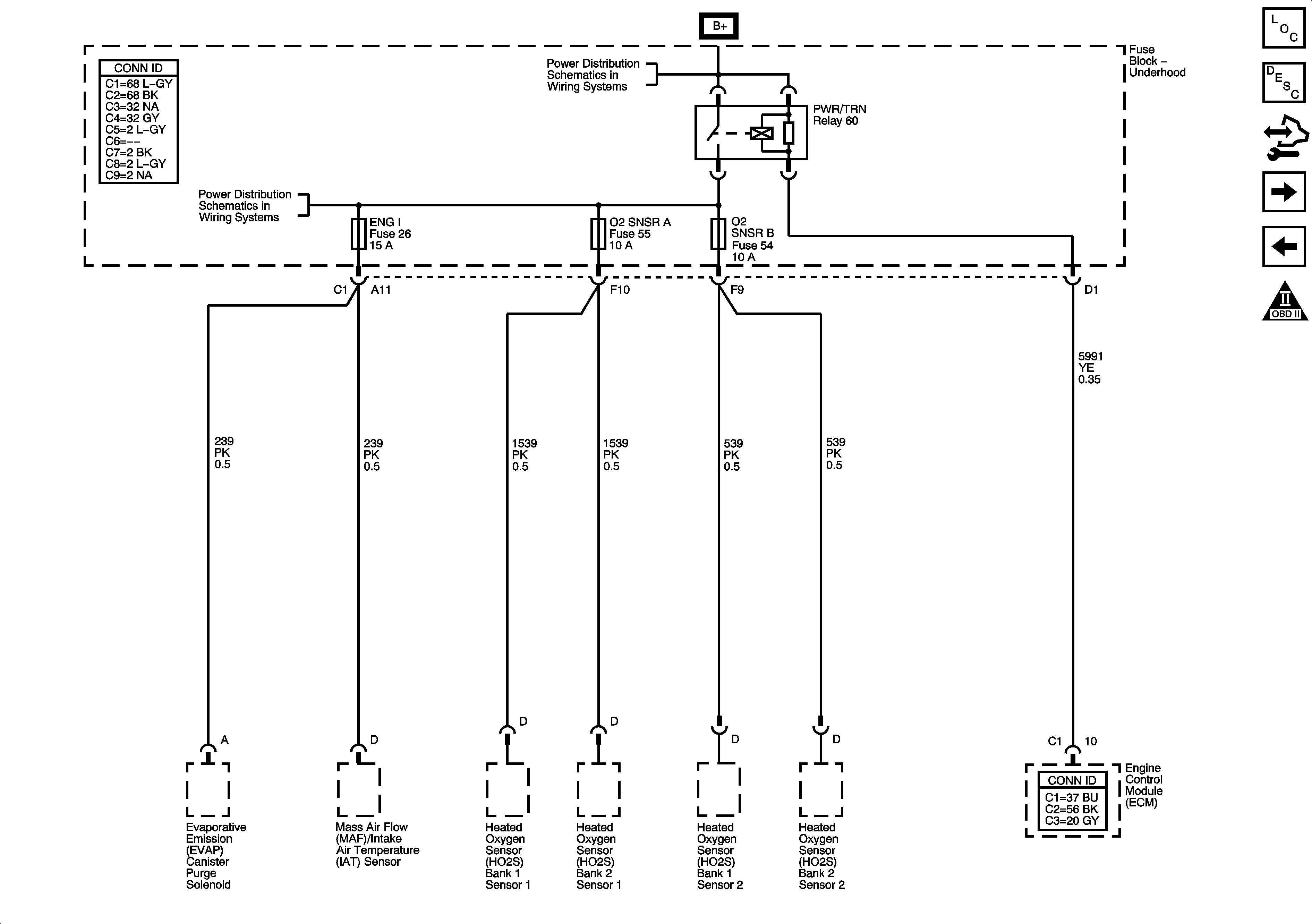
ENG I, ETC, INJA, INJB, O2 SNSR A, and O2 SNSR B Fuses - 5.3L/6.0L
Underhood Fuse Block
Figure 3:

Underhood Fuse Block - PWR/TRN Realy - 2 of 2

Object Number: 1594040  Size: FS
Master Electrical Component List
Engine Control Module Description
Control Module References
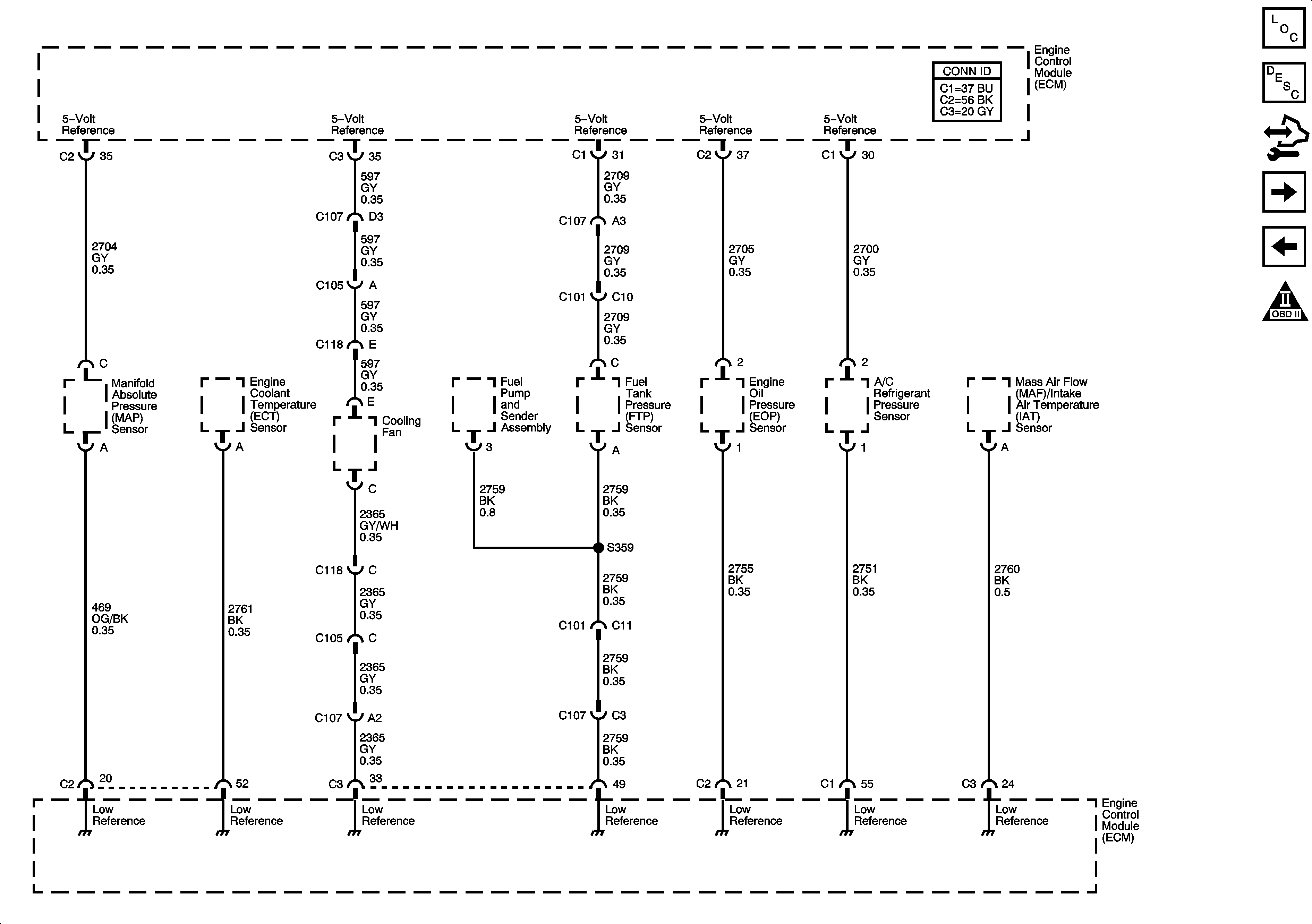
Engine Data Sensors - 5-Volt and Low Reference
Underhood Fuse Block - PWR/TRN Relay - 1 of 2
Engine Controls Schematic Icons
ENG I, ETC, INJA, INJB, O2 SNSR A, and O2 SNSR B Fuses - 5.3L/6.0L
Underhood Fuse Block
Figure 4:

Engine Data Sensors - 5-Volt Low Reference

Object Number: 1594041  Size: FS
Master Electrical Component List
Engine Control Module Description
Control Module References
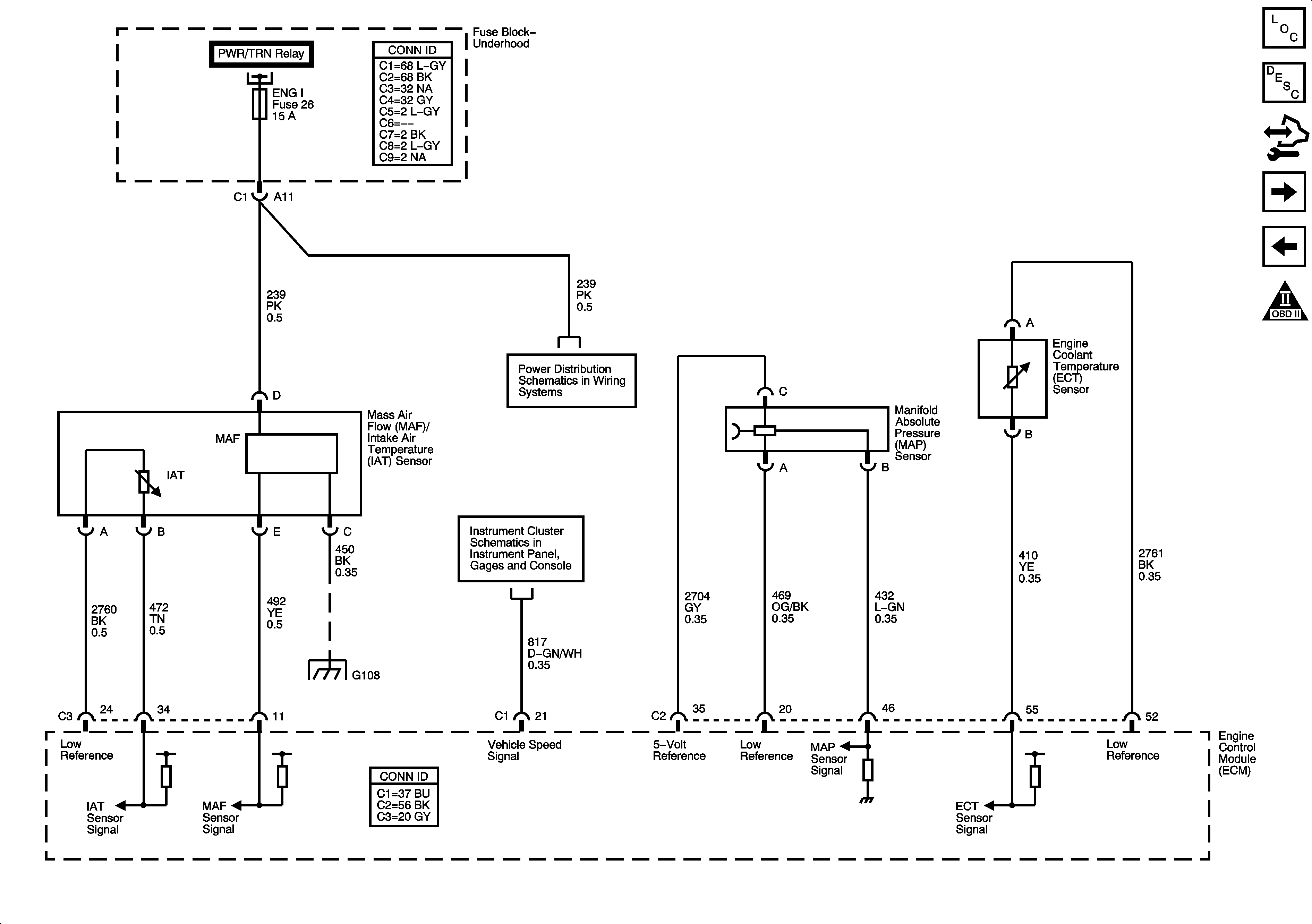
Engine Data Sensors - MAF, Pressure, Temperature, and VSS
Underhood Fuse Block - PWR/TRN Relay - 2 of 2
Engine Controls Schematic Icons
Figure 5:

Engine Data Sensors - MAF, Pressure, Temperature, and VSS


Object Number: 1594043  Size: FS
Master Electrical Component List
Engine Control Module Description
Control Module References
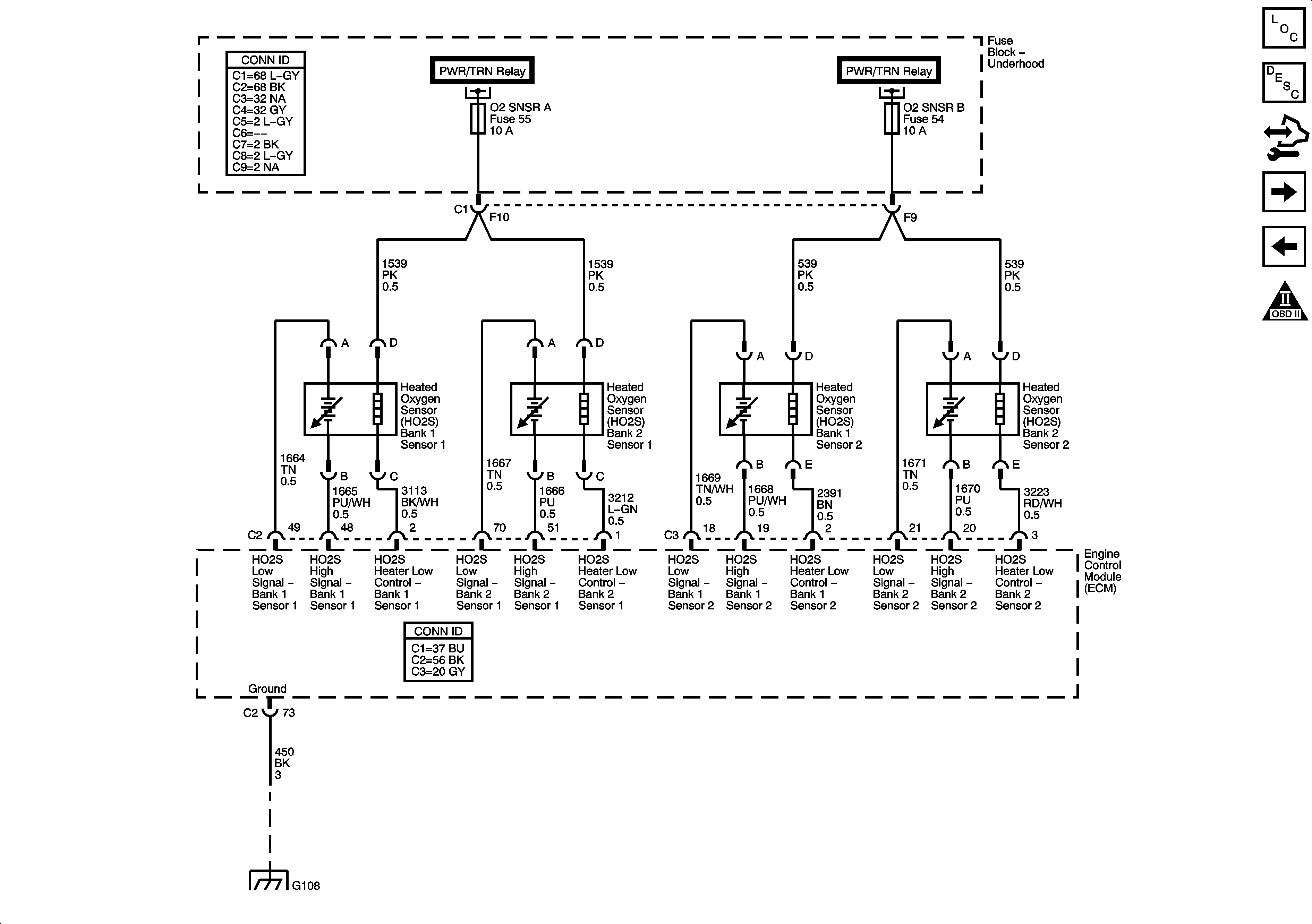
Engine Data Sensors - Oxygen Sensors
Engine Data Sensors - 5-Volt and Low Reference
Engine Controls Schematic Icons
Underhood Fuse Block - PWR/TRN Relay - 2 of 2
ENG I, ETC, INJA, INJB, O2 SNSR A, and O2 SNSR B Fuses - 5.3L/6.0L
Gages
G108
Figure 6:

Engine Data Sensors - Oxygen Sensors


Object Number: 1594045  Size: FS
Master Electrical Component List
Engine Control Module Description
Control Module References
Engine Data Sensors - Throttle Actuator Controls
Engine Data Sensors - MAF, Pressure, Temperature, and VSS
Engine Controls Schematic Icons
Underhood Fuse Block - PWR/TRN Relay - 2 of 2
G108
Figure 7:

Engine Data Sensors - Throttle Actuator Controls


Object Number: 1594046  Size: FS
Master Electrical Component List
Throttle Actuator Control (TAC) System Description
Control Module References
Ignition Controls - Ignition Coils 1,3,5, and 7
Engine Data Sensors - Oxygen Sensors
Engine Controls Schematic Icons
5.3L/6.0L
Figure 8:

Ignition Controls - Ignition Coils 1, 3, 5, and 7
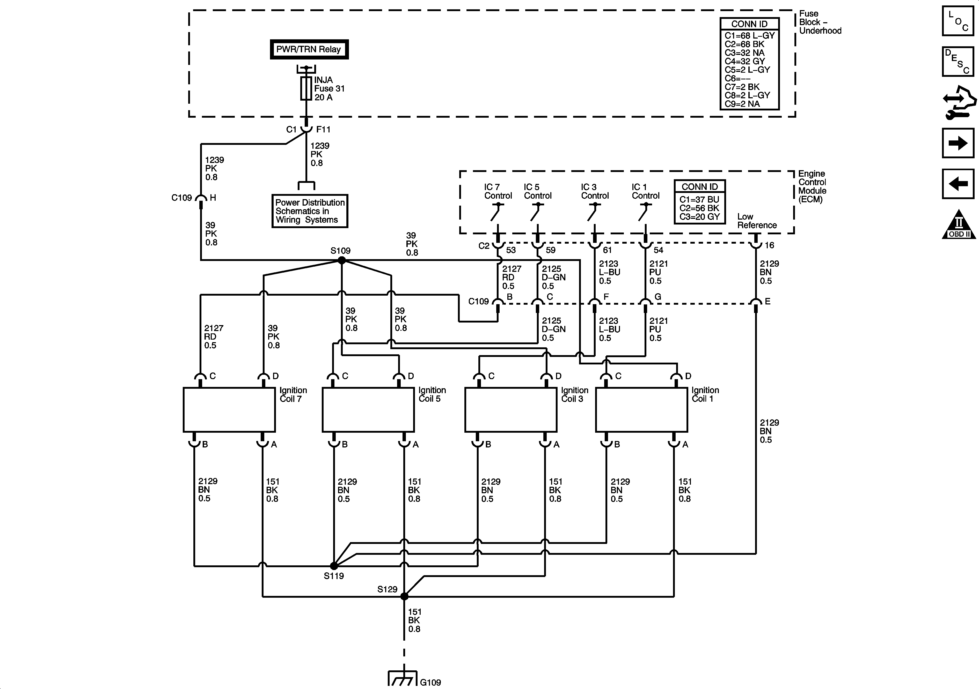

Object Number: 1594047  Size: FS
Master Electrical Component List
Engine Control Module Description
Control Module References
Ignition Controls - Ignition Coils 2, 4, 6, and 8
Engine Data Sensors - Throttle Actuator Controls
Engine Controls Schematic Icons
Underhood Fuse Block - PWR/TRN Relay - 1 of 2
ENG I, ETC, INJA, INJB, O2 SNSR A, and O2 SNSR B Fuses - 5.3L/6.0L
G109
Figure 9:

Ignition Controls - Ignition System Coils 2, 4, 6, and 8
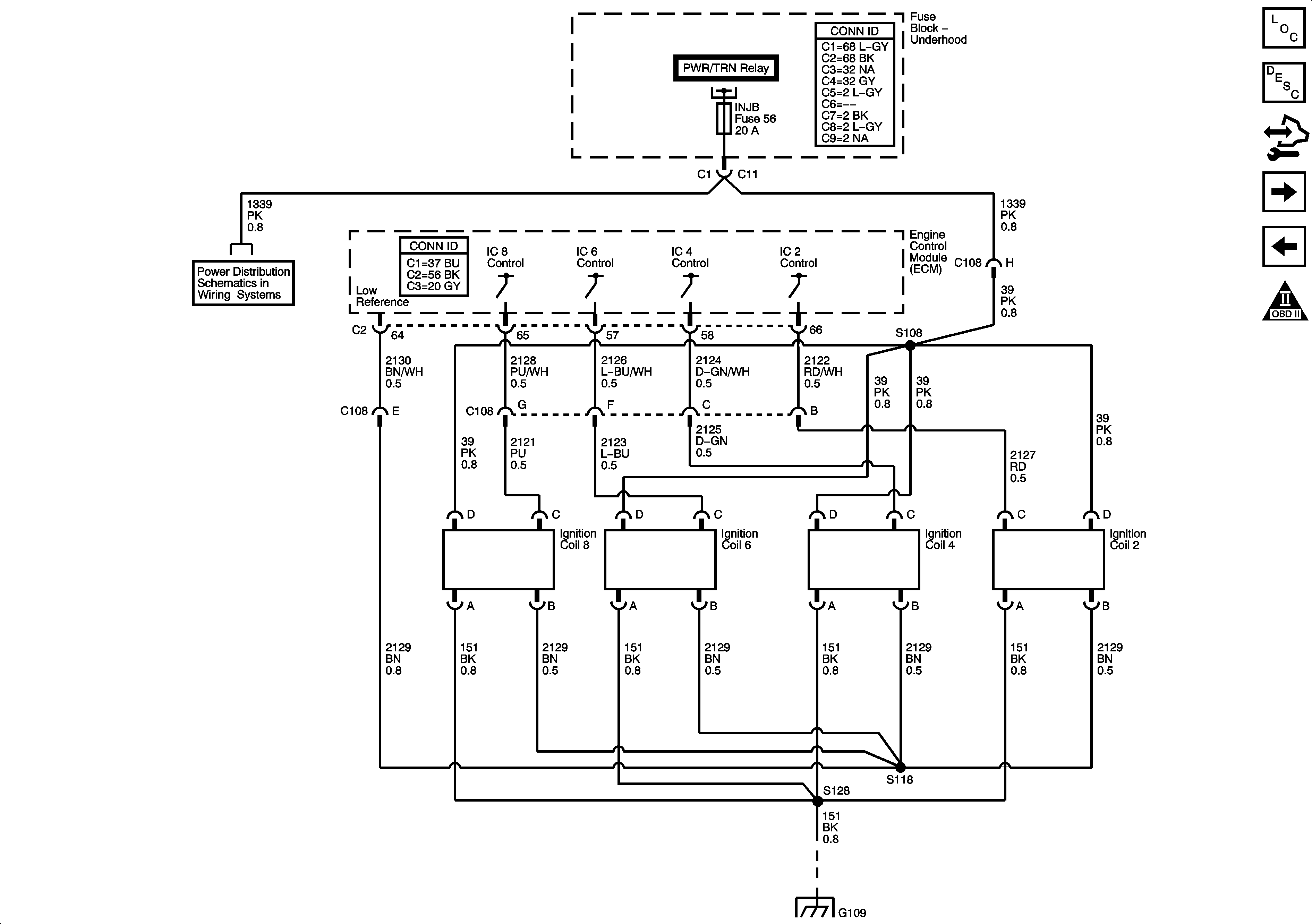

Object Number: 1594048  Size: FS
Master Electrical Component List
Engine Control Module Description
Control Module References
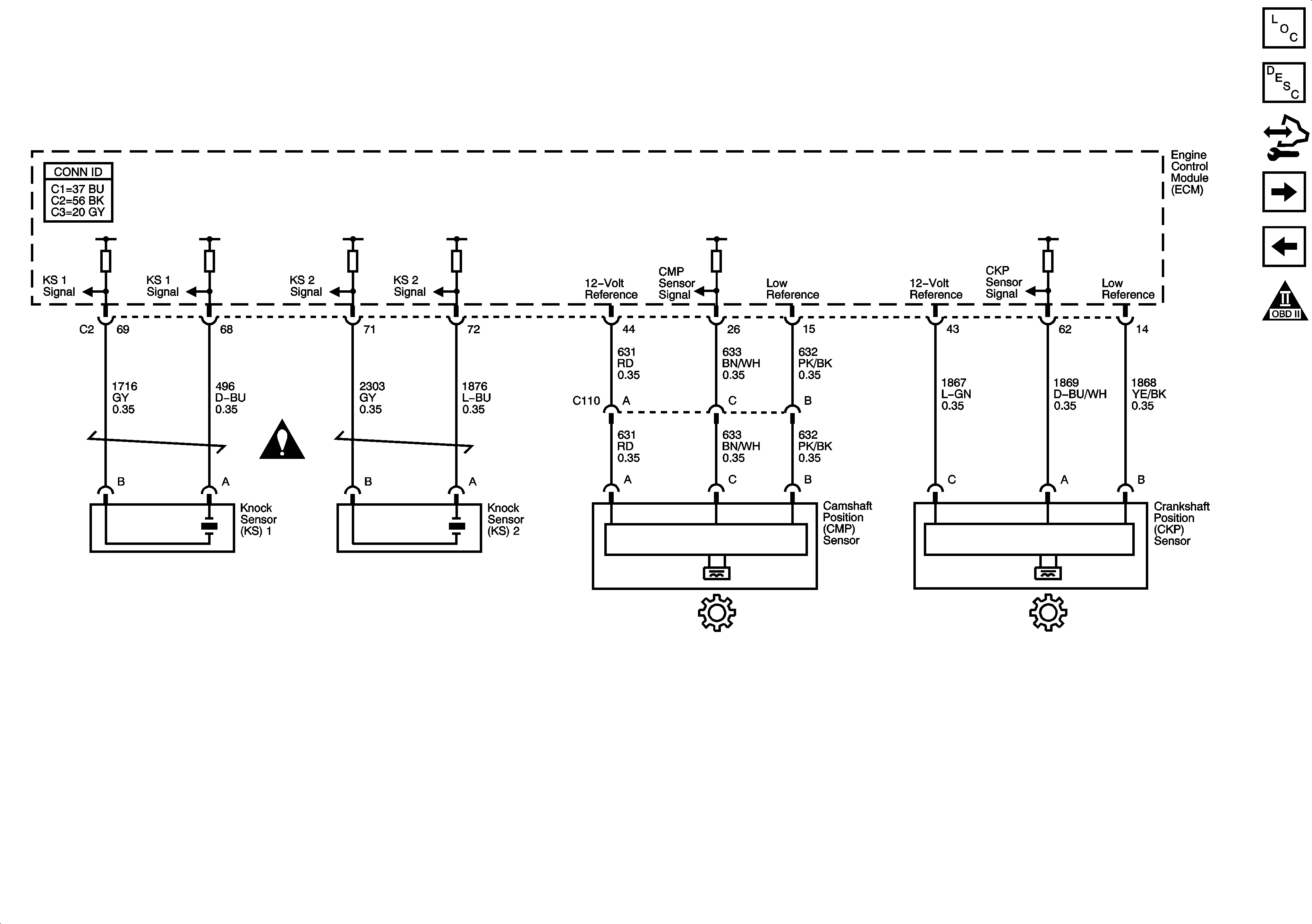
Ignition Controls - Sensors
Ignition Controls - Ignition Coils 1,3,5, and 7
Engine Controls Schematic Icons
Underhood Fuse Block - PWR/TRN Relay - 1 of 2
ENG I, ETC, INJA, INJB, O2 SNSR A, and O2 SNSR B Fuses - 5.3L/6.0L
G109
Figure 10:

Ignition Controls - Sensors


Object Number: 1594049  Size: FS
Master Electrical Component List
Knock Sensor (KS) System Description
Control Module References
Fuel Controls - Fuel Pump and Fuel Injectors
Ignition Controls - Ignition Coils 2, 4, 6, and 8
Engine Controls Schematic Icons
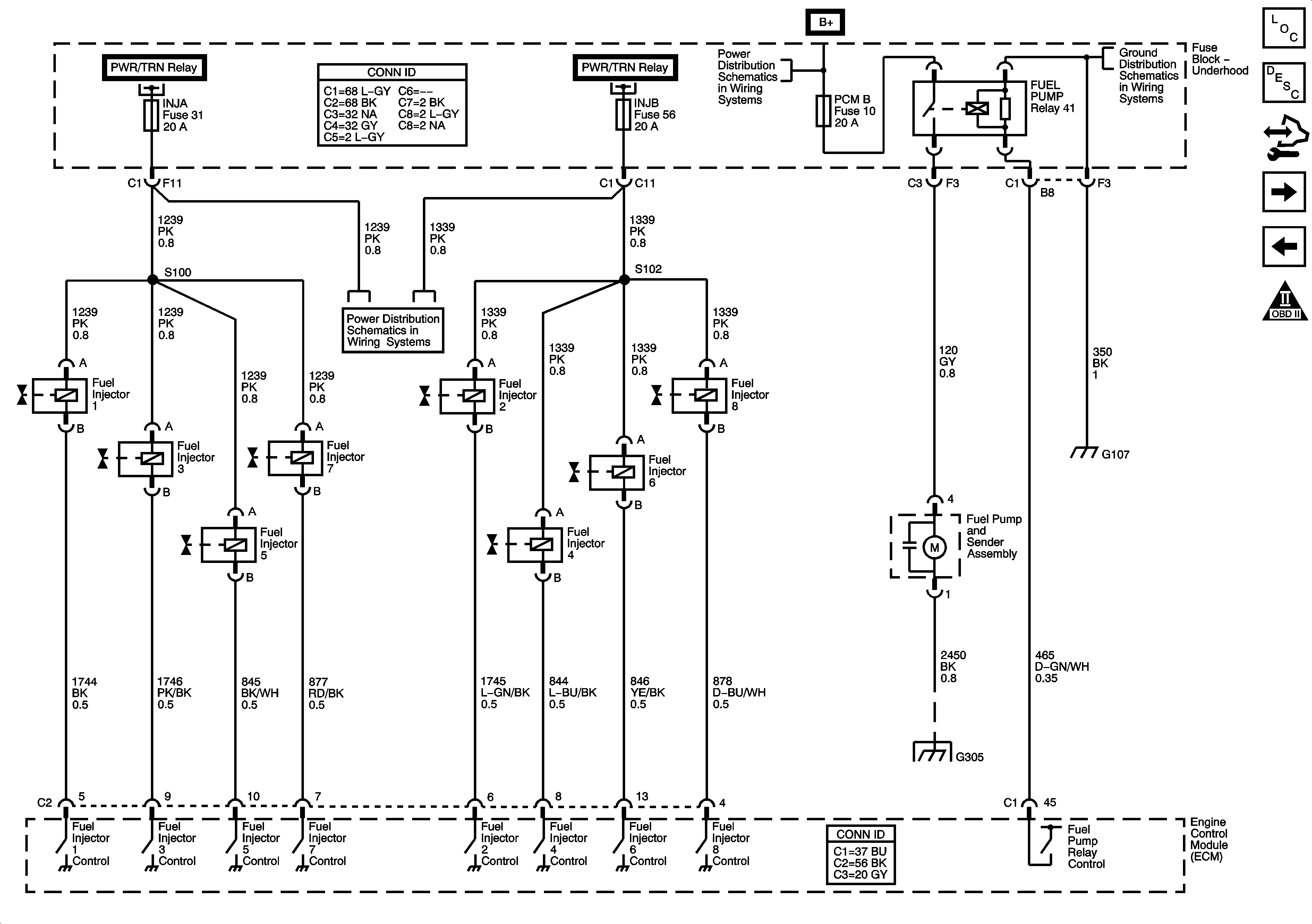
Figure 11:

Fuel Controls - Fuel Pump and Fuel Injectors


Object Number: 1594050  Size: FS
Master Electrical Component List
Fuel System Description
Control Module References
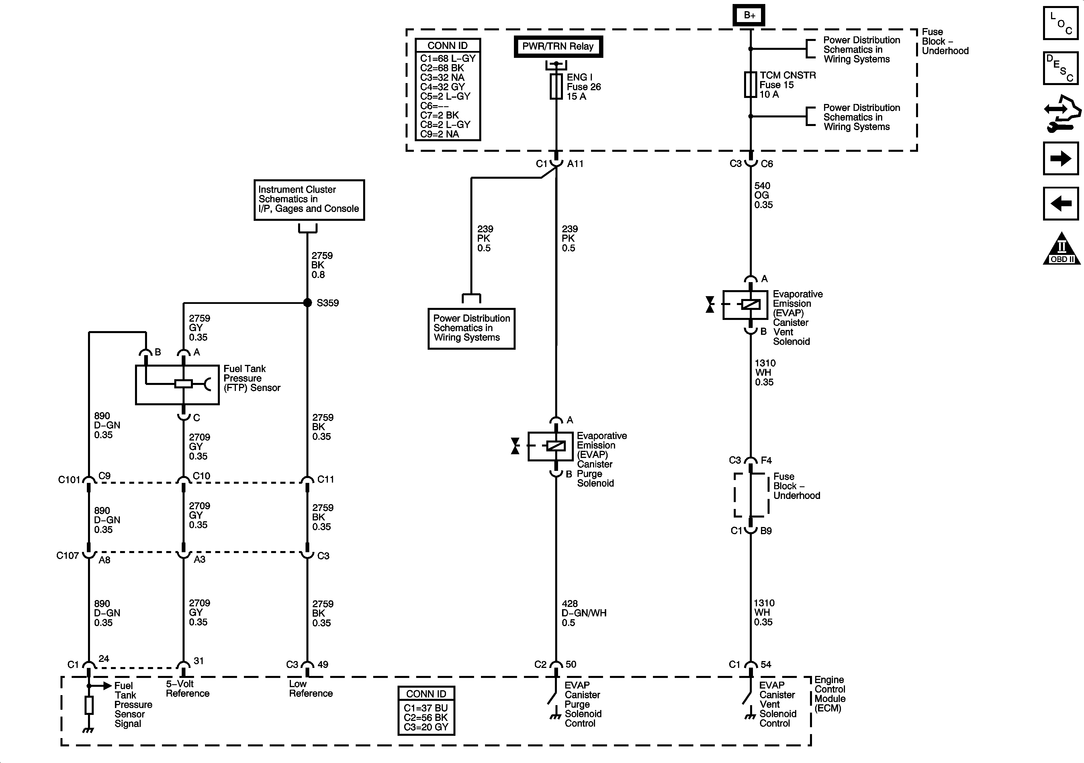
Fuel Controls - EVAP Controls
Ignition Controls - Sensors
Engine Controls Schematic Icons
Underhood Fuse Block - PWR/TRN Relay - 1 of 2
Underhood Fuse Block
G104, G105, and G107
ENG I, ETC, INJA, INJB, O2 SNSR A, and O2 SNSR B Fuses - 5.3L/6.0L
G201 - 2 of 2, and G305
Figure 12:

Fuel Controls - EVAP Controls


Object Number: 1594051  Size: FS
Master Electrical Component List
Evaporative Emission Control System Description
Control Module References
Controlled/Monitored Subsystem References
Fuel Controls - Fuel Pump and Fuel Injectors
Engine Controls Schematic Icons
Fuel Gage
ENG I, ETC, INJA, INJB, O2 SNSR A, and O2 SNSR B Fuses - 5.3L/6.0L
Underhood Fuse Block - PWR/TRN Relay - 2 of 2
Underhood Fuse Block
AUX PWR 1, RR HVAC, SUNROOF, TBC 2, TBC 3, TBC 4, TBC 5, and TCM CNSTR Fuses
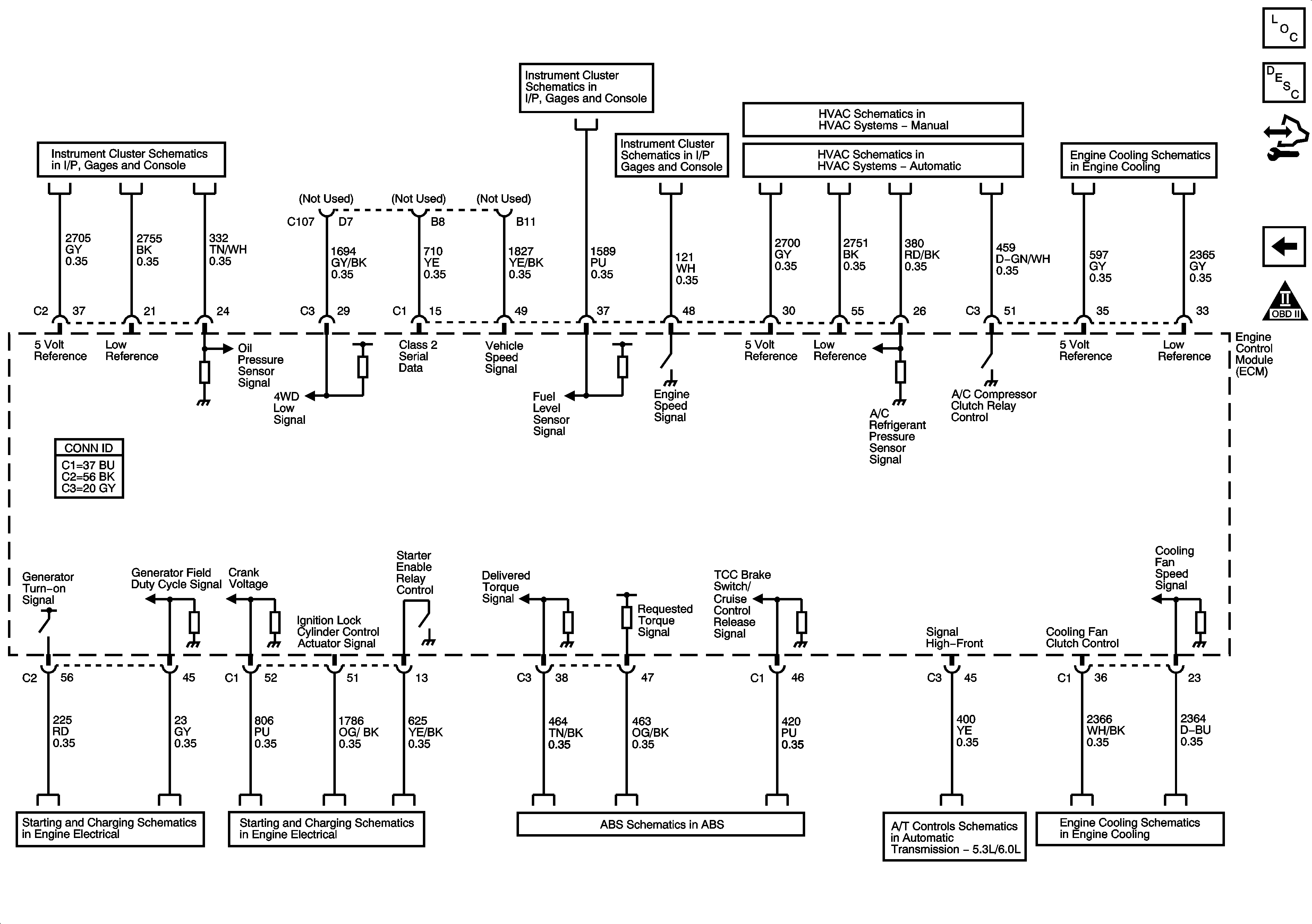
Figure 13:

Controlled/Monitored Subsystem References


Object Number: 1594052  Size: FS
Master Electrical Component List
Engine Control Module Description
Control Module References
Fuel Controls - EVAP Controls
Engine Controls Schematic Icons
Gages
Fuel Gage
Gages
Compressor Controls
Compressor Controls
Engine Cooling Schematics
Charging System
Starting System
EBCM Power, Ground, Serial Data, Indicator, and Signal Circuits
PNP Switch and VSS
Engine Cooling Schematics