Tools Required
J 42640 Steering Column Lock Pin
Removal Procedure
- Turn the steering wheel so that the front wheels are pointing straight ahead.
- Turn the ignition switch to the lock position and remove the key.
- Lock the steering column through the access hole in the lower steering column trim cover using J 42640 .
- Raise and support the vehicle. Refer to Lifting and Jacking the Vehicle .
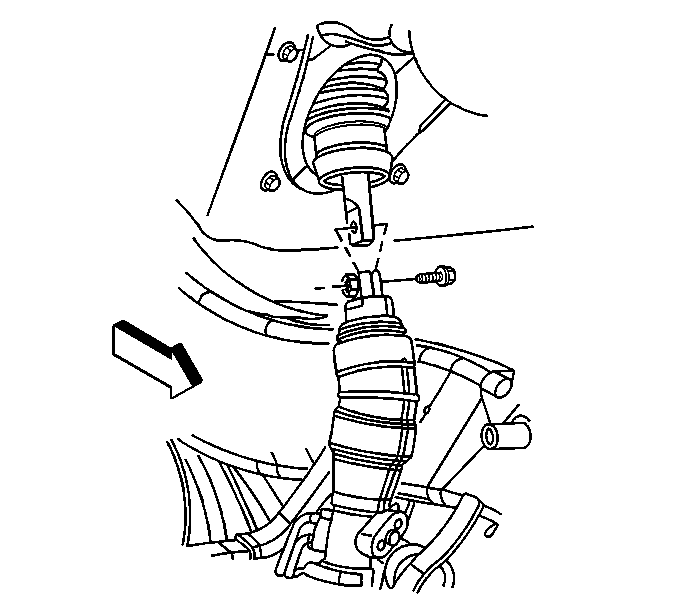
- Disconnect the upper intermediate shaft boot from the lower intermediate shaft boot to gain access to the upper intermediate shaft to lower intermediate pinch bolt.
- Remove the lower intermediate shaft to upper intermediate shaft pinch bolt.
- Disconnect the lower intermediate shaft from the upper intermediate shaft.
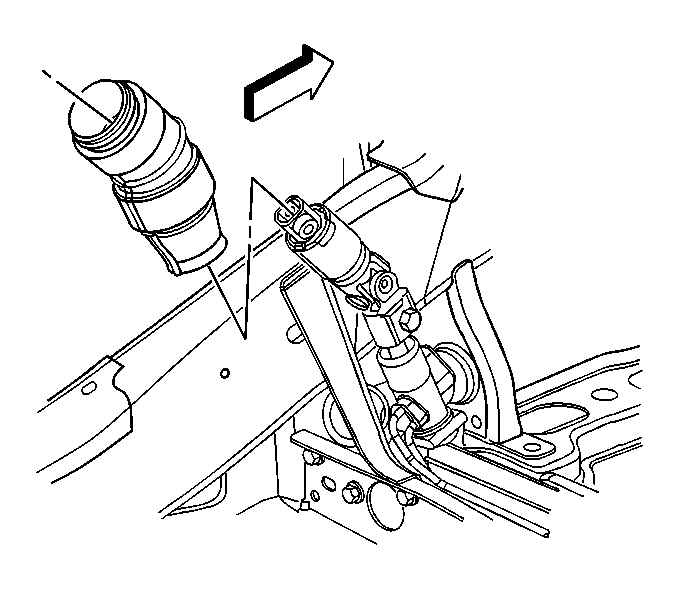
- Disconnect the lower intermediate shaft boot from the power steering gear and remove intermediate shaft boot from the vehicle.
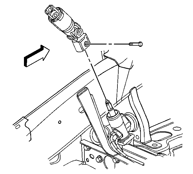
- Remove the lower intermediate shaft to the power steering gear input shaft pinch bolt.
- Disconnect the lower intermediate shaft from the power steering gear.
- Remove the lower intermediate shaft from the vehicle.
Notice: The front wheels of the vehicle must be maintained in the straight ahead position and the steering column must be in the LOCK position before disconnecting the steering column or intermediate shaft. Failure to follow these procedures will cause improper alignment of some components during installation and result in damage to the SIR coil assembly.

Important: Note the relationship of the intermediate shaft to the power steering gear and the intermediate shaft to the steering column in order to ensure proper installation.
Installation Procedure
- Install the lower intermediate shaft to the vehicle.
- Connect the lower intermediate shaft to the power steering gear.
- Remove all traces of the original adhesive patch.
- Clean the threads of the bolt with denatured alcohol or equivalent and allow to dry.
- Apply threadlocker GM P/N 12345382 (Canadian P/N 10953489) or LOCTITE™ 222.
- Install the lower intermediate shaft to the power steering gear input shaft pinch bolt.
- Install the lower intermediate shaft boot and connect the lower intermediate shaft boot to the power steering gear.
- Connect the lower intermediate shaft to the upper intermediate shaft.
- Remove all traces of the original adhesive patch.
- Clean the threads of the bolt with denatured alcohol or equivalent and allow to dry.
- Apply threadlocker GM P/N 12345382 (Canadian P/N 10953489) or LOCTITE™ 222.
- Install the lower intermediate shaft to the upper intermediate shaft pinch bolt.
- Connect the upper intermediate shaft boot to the lower intermediate shaft boot.
- Lower the vehicle.
- Unlock the steering column by removing J 42640 from the steering column lower trim cover access hole.
Notice: Refer to Fastener Notice in the Preface section.
Important: Perform the following procedure before installing the bolt.
Tighten
Tighten the lower intermediate shaft to the power steering gear input shaft pinch bolt to 40 N·m (29 lb ft).
Important: Perform the following procedure before installing the bolt.
Tighten
Tighten the lower intermediate shaft to the upper intermediate shaft pinch bolt to 50 N·m (37 lb ft).
Important: The upper intermediate shaft boot must completely cover the white insert of the lower intermediate shaft boot to ensure proper sealing.
