For 1990-2009 cars only
Front Wheel Hub, Bearing, and Seal Replacement RWD
Removal Procedure
- Raise and support the vehicle. Refer to Lifting and Jacking the Vehicle .
- Remove the tire and wheel. Refer to Tire and Wheel Removal and Installation .
- Remove the brake rotor. Refer to Front Brake Rotor Replacement .
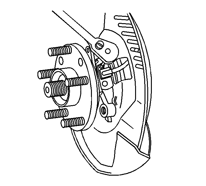
- Remove the ABS sensor mounting bolt from the wheel hub and bearing.
- Remove the ABS sensor from the wheel hub and bearing.
- Remove the wheel hub and bearing to the steering knuckle mounting bolts.
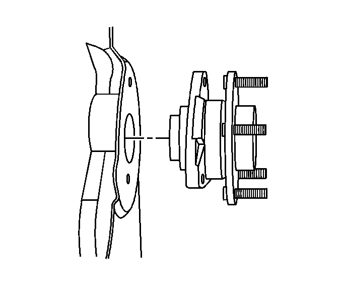
- Remove the wheel hub and bearing from the steering knuckle.
- Remove the splash shield from the steering knuckle.
Installation Procedure
- Install the splash shield to the steering knuckle. Align the splash shield to the steering knuckle threaded holes.
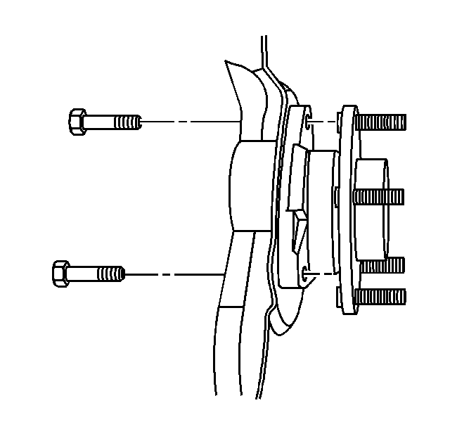
- Install the wheel hub and bearing to the steering knuckle. Align the threaded holes.
- Install the wheel hub and bearing to the steering knuckle mounting bolts.
- Install the ABS sensor to the wheel hub and bearing.
- Install the ABS sensor mounting bolt to the wheel hub and bearing.
- Install the brake rotor. Refer to Front Brake Rotor Replacement .
- Install the tire and wheel. Refer to Tire and Wheel Removal and Installation .
- Lower the vehicle.
Notice: Refer to Fastener Notice in the Preface section.
Tighten
Tighten the wheel hub and bearing mounting bolts to 105 N·m (77 lb ft).
Tighten
Tighten the ABS sensor to the wheel hub and bearing mounting bolt to 18 N·m (13 lb ft).
Front Wheel Hub, Bearing, and Seal Replacement 4WD
Removal Procedure
- Remove the tire and wheel center cap.
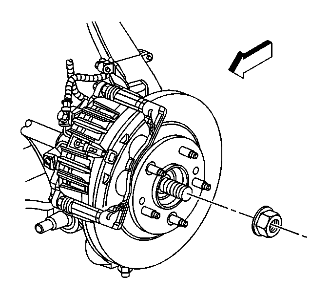
- Remove the drive axle nut.
- Raise and support the vehicle. Refer to Lifting and Jacking the Vehicle .
- Remove the tire and wheel. Refer to Tire and Wheel Removal and Installation .
- Remove the brake rotor. Refer to Front Brake Rotor Replacement .
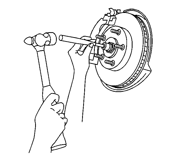
- Disengage the wheel drive shaft from the wheel hub and bearing. Place a brass drift against the outer end of the wheel drive shaft in order to protect the wheel drive shaft threads. Sharply strike the brass drift with the hammer. Do not attempt to remove the wheel drive shaft from the wheel hub and bearing at this time.
- Remove the ABS sensor mounting bolt from the wheel hub and bearing.
- Remove the ABS sensor from the wheel hub and bearing.
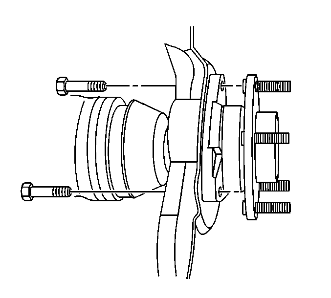
- Remove the wheel hub and bearing to the steering knuckle mounting bolts.
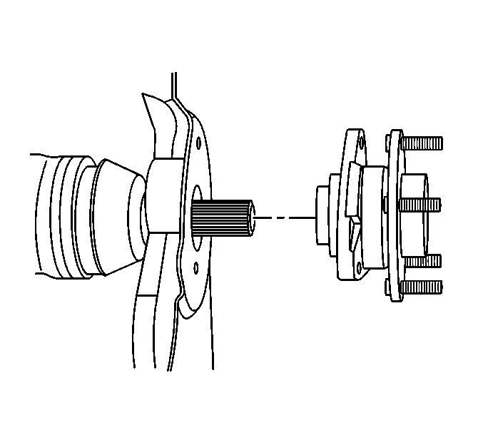
- Remove the wheel hub and bearing from the steering knuckle.
- Remove the splash shield from the steering knuckle.
Installation Procedure
- Install the splash shield to the steering knuckle. Align the splash shield to the steering knuckle threaded holes.
- Install the wheel hub and bearing to the steering knuckle. Align the threaded holes.
- Install the wheel hub and bearing to the steering knuckle mounting bolts.
- Install the ABS sensor to the wheel hub and bearing.
- Install the ABS sensor mounting bolt to the wheel hub and bearing.
- Install the brake rotor. Refer to Front Brake Rotor Replacement .
- Install the tire and wheel. Refer to Tire and Wheel Removal and Installation .
- Lower the vehicle.
- Install the drive axle nut and draw the hub and bearing onto the axle.
- Install the tire and wheel center cap.
Notice: Refer to Fastener Notice in the Preface section.
Tighten
Tighten the wheel hub and bearing mounting bolts to 105 N·m (77 lb ft).
Tighten
Tighten the ABS sensor to the wheel hub and bearing mounting bolt to 18 N·m (13 lb ft).
Tighten
Tighten the drive axle nut to 140 N·m (103 lb ft).
