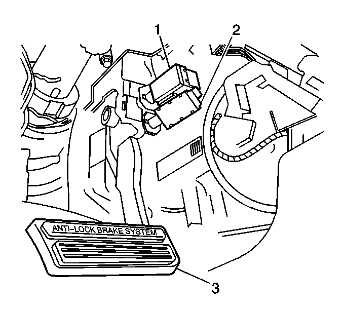
For 1990-2009 cars only
Important: Do not depress the brake pedal during the adjustment procedure.
- Remove the left closeout/insulator panel. Refer to Instrument Panel Insulator Panel Replacement - Left Side in Instrument Panel, Gages and Console.
- Rotate the switch (1) counter-clockwise in order to release the switch from the retainer.
- Insert the switch (1) into the retainer until the switch is fully seated against the brake pedal arm.
- Rotate the switch clockwise in order to lock the switch into position.
- Install the left closeout/insulator panel. Refer to Instrument Panel Insulator Panel Replacement - Left Side in Instrument Panel, Gages and Console.

Measure
Measure the distance from the end of the barrel on the switch to the
pedal arm, ensure that the clearance is 1.5-1.7 mm (1/16 in).
If the distance is not correct, perform step 1 and step 2
again.
Measure
The following pedal travel statement may be used in order to inspect
for proper adjustment of the release switch:
| • | The release switch assembly must be closed at 3.5-12.5 mm (1/8-1/2 in) brake pedal travel, measured at the centerline of the brake pedal assembly. |
| • | Nominal actuation of the release assembly contacts is about 4.5 mm (3/16 in). |
