Air Cleaner Assembly Replacement VIN K
Removal Procedure
Notice: Do not touch the connector pins or soldered components on the circuit board in order to prevent possible electrostatic discharge (ESD) damage to the PCM.
Notice: Turn the ignition OFF when installing or removing the PCM connectors and disconnecting or reconnecting the power to the PCM (battery cable, PCM pigtail, PCM fuse, jumper cables, etc.) in order to prevent internal PCM damage.
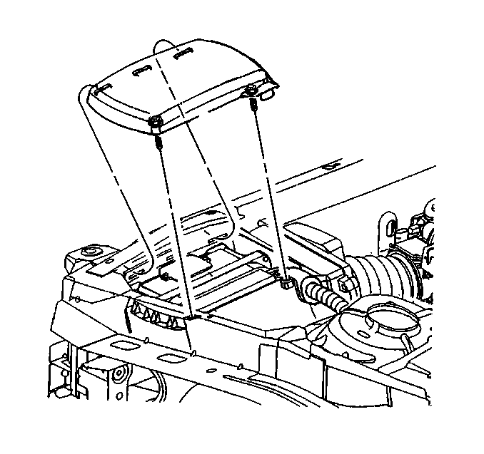
- Remove the screws from the air cleaner top cover.
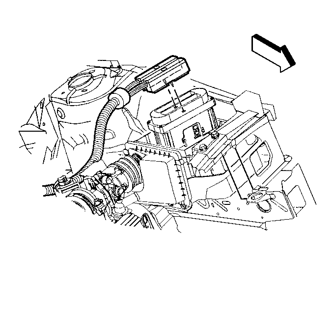
- Remove the PCM from the air cleaner. Refer to Powertrain Control Module Replacement/Programming .
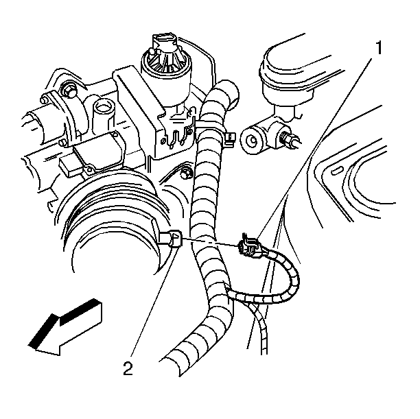
- Remove the IAT sensor connector (1) from the IAT sensor (2).
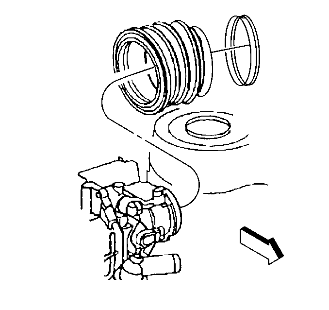
- Loosen the intake air duct from the Mass Air Flow Sensor end of the intake air duct.
- Remove the intake air duct from the throttle body.
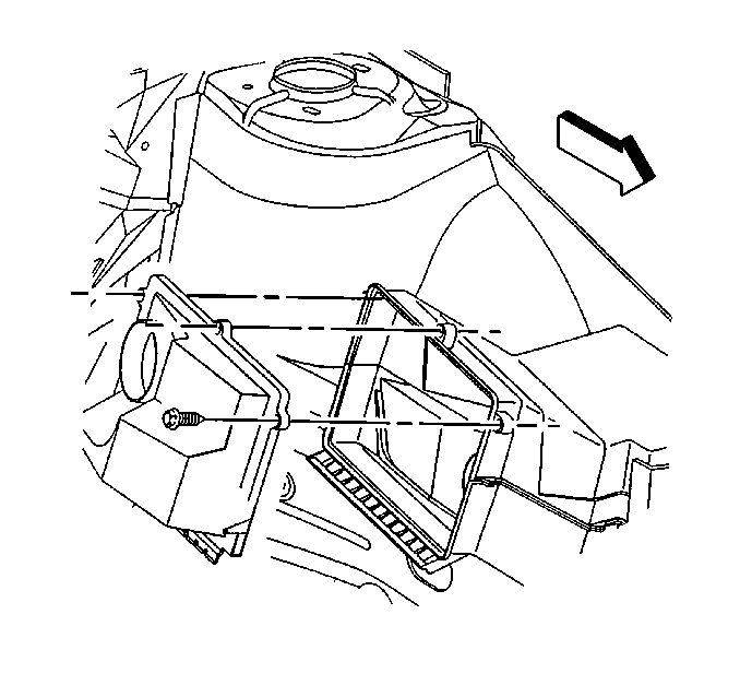
- Remove the screws from the air cleaner.
- Inspect air cleaner element.
- Remove any loose debris that may be found laying in the base of the air cleaner.
- Remove the air cleaner assembly.
Installation Procedure
- Install a new air cleaner element into the air cleaner assembly.
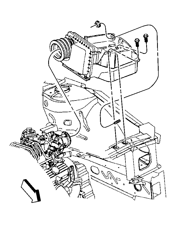
- Install the air cleaner assembly to the engine compartment over the stud on the inner fender.
- Inspect to see that the coolant recovery hose is not trapped under the air cleaner assembly.
- Install the air cleaner assembly to the radiator support with the bolts.
- Secure the air cleaner assembly to the stud on the inner fender with the nut.
- Install the PCM in the air cleaner. Refer to Powertrain Control Module Replacement/Programming .
- Install the screws in the air cleaner top cover.
- Install the intake air duct over the throttle body, being careful to ensure that the intake air duct is secure around the entire outer edge of the throttle body.
- Install the screws from the air cleaner cover.
- Connect the IAT sensor connector (1) to the IAT sensor (2).
Notice: Use the correct fastener in the correct location. Replacement fasteners must be the correct part number for that application. Fasteners requiring replacement or fasteners requiring the use of thread locking compound or sealant are identified in the service procedure. Do not use paints, lubricants, or corrosion inhibitors on fasteners or fastener joint surfaces unless specified. These coatings affect fastener torque and joint clamping force and may damage the fastener. Use the correct tightening sequence and specifications when installing fasteners in order to avoid damage to parts and systems.
Tighten
Tighten the bolts to 4 N·m (35 lb in).
| 5.1. | Push to secure the nut. |
| 5.2. | Assure that the nut is fully seated. |
Important: The outlet of the air cleaner assembly and the intake air duct must be lined up to the throttle body when completely installed. Misalignment may cause incorrect air flow readings resulting in MIL illumination or a driveabilty concern.
Tighten
Tighten the screws to 2 N·m (18 lb in).
Tighten
Tighten the clamp assembly to 2 N·m 18 lb in.
Tighten
Tighten the screws to 2 N·m (18 lb in).

Air Cleaner Assembly Replacement VIN 1
Removal Procedure
- Disconnect the negative battery cable. Refer to Battery Negative Cable Disconnection and Connection in Engine Electrical.
- Remove the screws from the air cleaner top cover.
- Remove the PCM from the air cleaner. Refer to Powertrain Control Module Replacement/Programming .
- Remove the IAT sensor connector (1) from the IAT sensor (2).
- Loosen the intake air duct from the Mass Air Flow Sensor end of the intake air duct.
- Remove the intake air duct from the throttle body.
- Remove the screws from the air cleaner.
- Inspect air cleaner element.
- Remove any loose debris that may be found laying in the base of the air cleaner.
- Remove the air cleaner assembly.

Caution: Before servicing any electrical component, the ignition and start switch must be in the OFF or LOCK position and all electrical loads must be OFF, unless instructed otherwise in these procedures. If a tool or equipment could easily come in contact with a live exposed electrical terminal, also disconnect the negative battery cable. Failure to follow these precautions may cause personal injury and/or damage to the vehicle or its components.


Installation Procedure
- Install a new air cleaner element into the air cleaner assembly.
- Install the air cleaner assembly to the engine compartment over the stud on the inner fender.
- Inspect to see that the coolant recovery hose is not trapped under the air cleaner assembly.
- Install the air cleaner assembly to the radiator support with the bolts.
- Secure the air cleaner assembly to the stud on the inner fender with the nut.
- Install the PCM from the air cleaner. Refer to Powertrain Control Module Replacement/Programming .
- Install the screws in the air cleaner top cover.
- Install the intake air duct over the throttle body, being careful to ensure that the intake air duct is secure around the entire outer edge of the throttle body.
- Install the screws from the air cleaner cover.
- Connect the IAT sensor connector (1) to the IAT sensor (2).
- Install the negative battery cable. Refer to Battery Negative Cable Disconnection and Connection in Engine Electrical.

Important : VIN 1 has a white drain tube under the PCM hosing and white inlet area.
Tighten
Tighten the bolts to 4 N·m (35 lb in).
| 5.1. | Push to secure the nut. |
| 5.2. | Assure that the nut is fully seated. |

Important: The outlet of the air cleaner assembly and the intake air duct must be lined up to the throttle body when completely installed. Misalignment may cause incorrect air flow readings resulting in MIL illumination or a driveabilty concern.
Notice: Use the correct fastener in the correct location. Replacement fasteners must be the correct part number for that application. Fasteners requiring replacement or fasteners requiring the use of thread locking compound or sealant are identified in the service procedure. Do not use paints, lubricants, or corrosion inhibitors on fasteners or fastener joint surfaces unless specified. These coatings affect fastener torque and joint clamping force and may damage the fastener. Use the correct tightening sequence and specifications when installing fasteners in order to avoid damage to parts and systems.
Tighten
Tighten the screws to 2 N·m (18 lb in).
Tighten
Tighten the clamp assembly to 2 N·m 18 lb in.
Tighten
Tighten the screws to 2 N·m (18 lb in).

