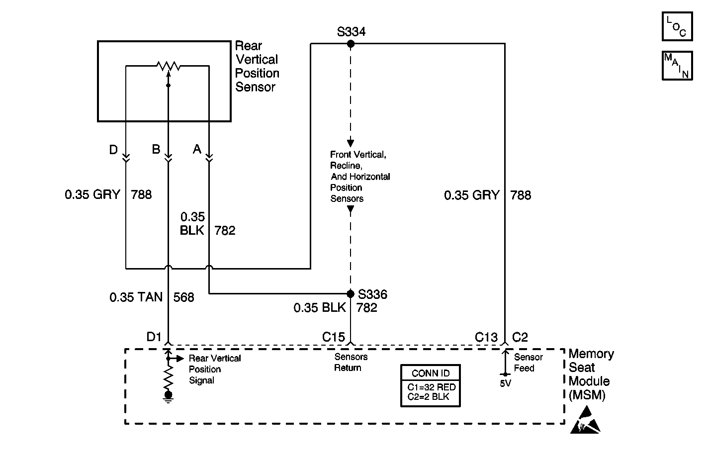
Circuit Description
The sensor that sets this diagnostic trouble code (DTC) is attached to the seat direction motor it monitors. The sensor is a potentiometer whose supply and ground are portions of the sensor 5 V supply bus and the ground bus provided by the memory seat module (MSM). The sensor analog output signal is wired directly to the MSM. The MSM checks the signal to determine seat motor position.
Conditions for Running the DTC
The MSM must be powered and can not have B1327-Battery Voltage Low set as an active DTC for this DTC to set.
Conditions for Setting the DTC
If the MSM sees the analog input from this sensor as either lower than 0.25 V or higher than 4.75 V during one cycle of checking the MSM inputs, the MSM sets this DTC.
Action Taken When the DTC Sets
The MSM disables the memory recall and easy exit/entry actuation commands of the motor monitored by the sensor. The motor will respond to manual actuation commands.
Conditions for Clearing the DTC
The MSM will clear the DTC as an active malfunction when the MSM sees the analog input from this sensor as between 0.25 V and 4.75 V during one cycle of checking the MSM inputs.
Diagnostic Aids
The position sensors use a common ground and common sensor return circuit.
Test Description
The numbers below refer to the step numbers on the diagnostic table.
Step | Action | Value(s) | Yes | No |
|---|---|---|---|---|
1 | Did you perform the Diagnostic System Check - Power Seat Systems? | -- | ||
Does the voltage measure within the specified range? | 4.6-5.2 V | |||
3 | Test the signal circuit of the sensor for a short to ground, high resistance, or an open. Refer to Circuit Testing and Wiring Repairs in Wiring Systems. Did you find and correct the condition? | |||
4 | Test the 5 volt reference circuit of the sensor for a high resistance or an open. Refer to Circuit Testing and Wiring Repairs in Wiring Systems. Did you find and correct the condition? | |||
5 | Test the sensor return circuit of the sensor for a high resistance or an open. Refer to Circuit Testing and Wiring Repairs in Wiring Systems. Did you find and correct the condition? | |||
6 | Inspect for poor connections at the harness connector of the sensor. Refer to Testing for Intermittent Conditions and Poor Connections and Connector Repairs in Wiring Systems. Did you find and correct the condition? | -- | ||
7 | Inspect for poor connections at the harness connector of the memory seat module. Refer to Testing for Intermittent Conditions and Poor Connections and Connector Repairs in Wiring Systems. Did you find and correct the condition? | -- | ||
8 | Replace the recline sensor. Refer to Seat Adjuster Motor Replacement - Rear Vertical . Did you complete the replacement? | -- | -- | |
9 | Replace the memory seat module. Refer to Memory Seat Control Module Replacement . Did you complete the replacement? | -- | -- | |
10 |
Does the DTC reset? | -- | System OK |
