Test Description
Caution: Wrap a shop towel around the fuel pressure connection in order to reduce the risk of fire and personal injury. The towel will absorb any fuel leakage that occurs during the connection of the fuel pressure gage. Place the towel in an approved container when the connection of the fuel pressure gage is complete.
-
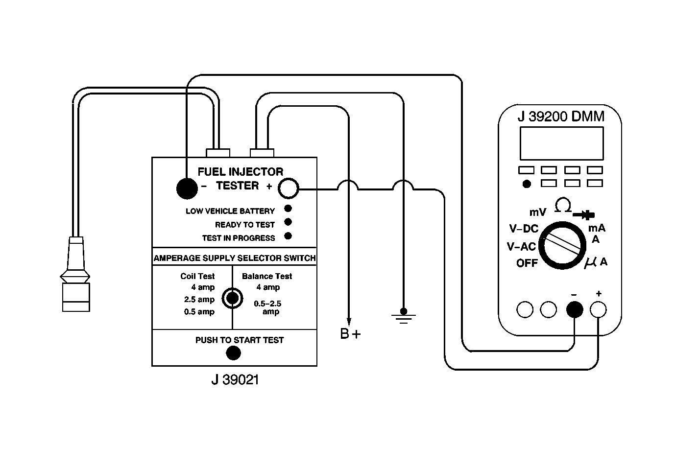
The engine coolant temperature affects the ability of the fuel injector tester to detect a faulty fuel injector.
-
The first second of the voltage displayed by the DMM may be inaccurate due to the initial current surge, therefore, record the lowest voltage displayed by the DMM after the first second of the test. The voltage displayed by the DMM should be within the specified range. Refer to the example. The voltage displayed by the DMM may increase throughout the test as the fuel injector windings warm and the resistance of the fuel injector windings changes. An erratic voltage reading (large fluctuations in voltage that do not stabilize) indicates an intermittent connection within the fuel injector.
Resistance Ohms | Voltage Specification at 10°C-35°C (50°F-95°F) | |
|---|---|---|
11.4-12.6 | 5.7-6.6 | |
Fuel Injector Number | Voltage Reading | Pass/Fail |
1 | 6.3 | P |
2 | 5.9 | P |
3 | 6.2 | P |
4 | 6.1 | P |
5 | 4.8 | F |
6 | 6.0 | P |
Step | Action | Values | Yes | No |
|---|---|---|---|---|
1 | Was the Powertrain On-Board Diagnostic (OBD) System Check performed? | -- | ||
Is the engine coolant temperature within the specified limits? | 10°C-35°C (50°F-95°F) | |||
Notice: In order to prevent flooding of a single cylinder and possible engine damage, relieve the fuel pressure before performing the fuel injector coil test procedure. Important:: Check the engine coolant temperature again to ensure that the correct chart is being used. Important:: The voltage reading may rise during the test. Did any fuel injector have an erratic voltage reading (large fluctuations in voltage that do not stabilize) or a voltage reading outside of the specified limits? | 5.7-6.6V | Go to Fuel Injector Balance Test with Special Tool or Fuel Injector Balance Test with Tech 2 | ||
4 | Replace the faulty fuel injectors. Refer to Fuel Injector Replacement . Is the action complete? | -- | Go to Fuel Injector Balance Test with Special Tool or Fuel Injector Balance Test with Tech 2 | -- |
