Step | Action | Yes | No |
|---|---|---|---|
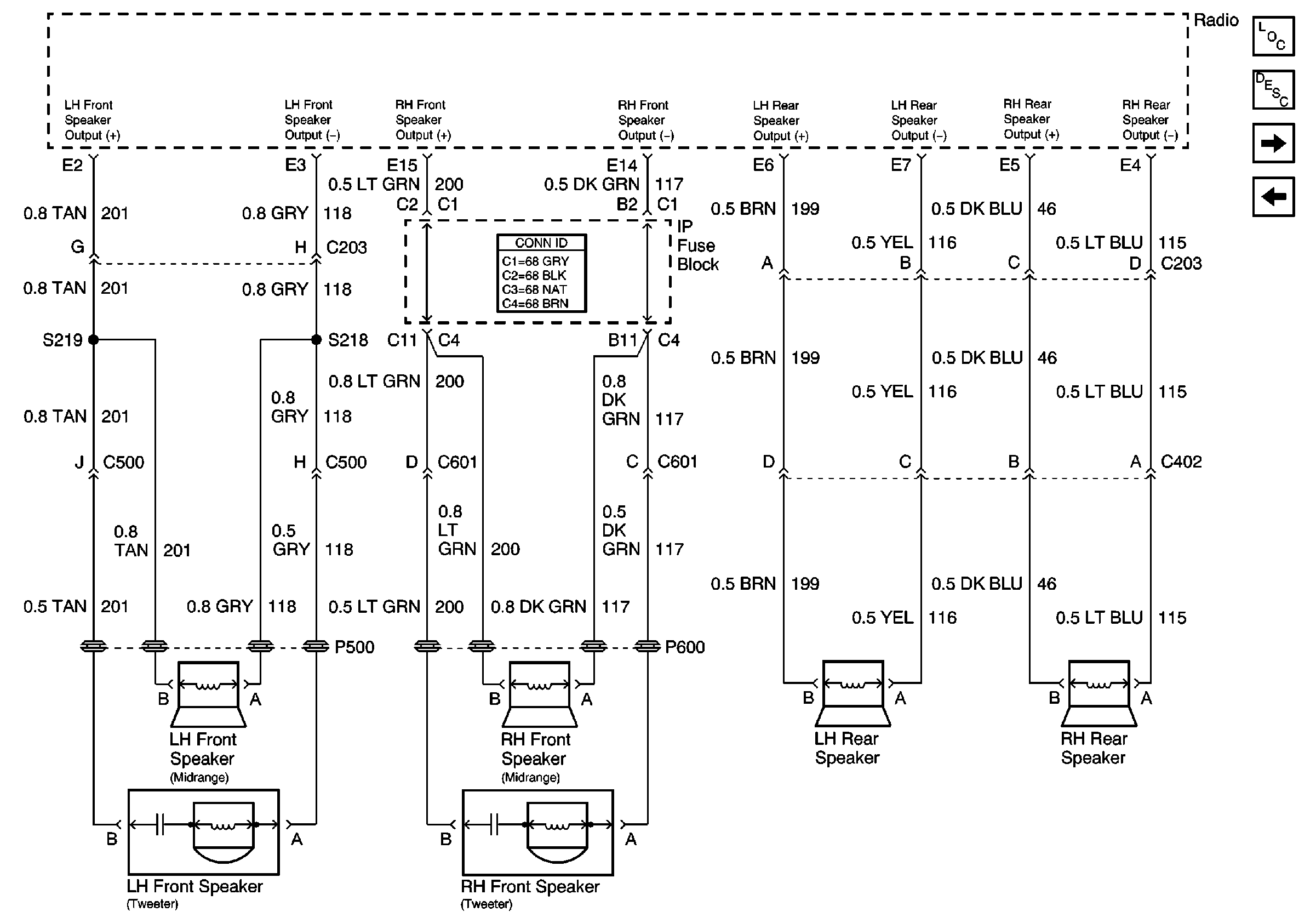
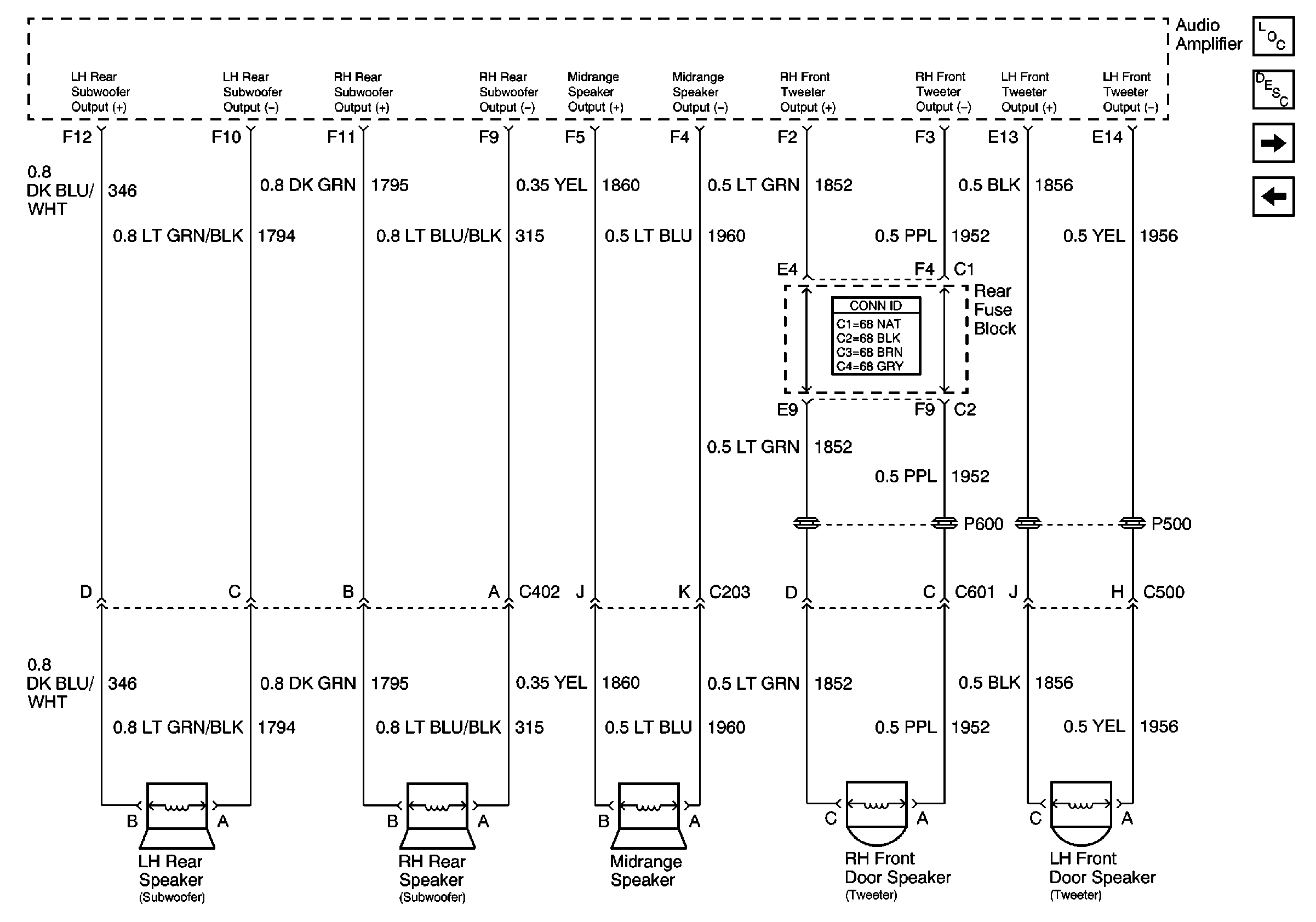
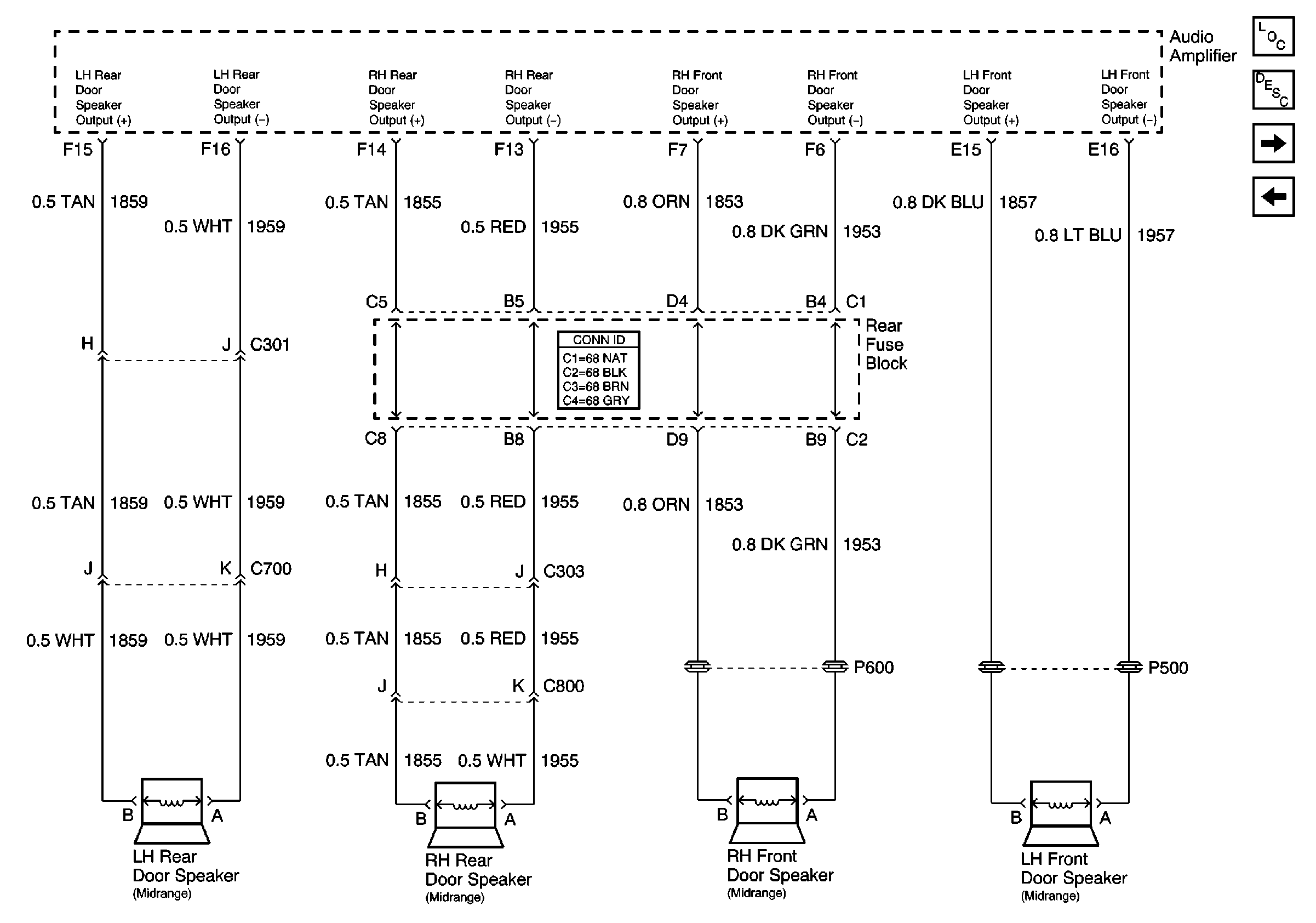
Schematic Reference:
| |||
1 | Did you review the audio descriptions and operations and perform the necessary inspections? | Go to Step 2 | Go to Symptoms |
2 |
Are all of the speakers inoperative? | Go to Step 8 | Go to Step 3 |
3 |
| Go to Testing for Intermittent Conditions and Poor Connections in Wiring Systems | Go to Step 4 |
4 | Measure the A/C voltage between the speaker connector terminals (speaker connected). Is A/C voltage measured? | -- | Go to Step 5 |
5 | Is the vehicle equipped with U99? | Go to Step 7 | Go to Step 8 |
6 | Test the signal input circuits of the appropriate speaker for an open or high resistance. Refer to Circuit Testing and Wiring Repairs in Wiring Systems. Did you find and correct the condition? | Go to Step 15 | Go to Step 9 |
7 | Test the signal input circuits of the appropriate speaker between the speaker and the amplifier for an open, high resistance, short to B+ or a short to ground. Refer to Circuit Testing and Wiring Repairs in Wiring Systems. Did you find and correct the condition? | Go to Step 15 | Go to Step 10 |
8 | Test all speaker output signal circuits from the radio for a short to B+ or a short to ground. Refer to Circuit Testing and Wiring Repairs in Wiring Systems. Did you find and correct the condition? | Go to Step 15 | Go to Step 11 |
9 | Inspect for poor connections at the harness connector of the radio. Refer to Testing for Intermittent Conditions and Poor Connections and Connector Repairs in Wiring Systems. Did you find and correct the condition? | Go to Step 15 | Go to Step 12 |
10 | Inspect for poor connections at the harness connector of the amplifier. Refer to Testing for Intermittent Conditions and Poor Connections and Connector Repairs in Wiring Systems. Did you find and correct the condition? v | Go to Step 15 | Go to Step 13 |
11 | Inspect for poor connections at the speaker. Refer to Testing for Intermittent Conditions and Poor Connections and Connector Repairs in Wiring Systems. Did you find and correct the condition? | Go to Step 15 | Go to Step 14 |
12 |
Important:: Perform the set up procedure for the radio. Replace the radio. Refer to Radio Replacement . Did you complete the repair? | Go to Step 15 | -- |
13 | Replace the amplifier. Refer to Radio Speaker Amplifier Replacement . Did you complete the repair? | Go to Step 15 | -- |
14 | Replace the speaker. Refer to Radio Front Speaker Replacement , Radio Rear Speaker Replacement , Radio Front Side Door Lower Speaker Replacement , Front Upper Speaker Replacement , and Radio Rear Side Door Speaker Replacement . Did you complete the replacement? | Go to Step 15 | -- |
15 | Operate the system in order to verify the repair. Did you correct the condition? | Go to Step 2 | System OK |


