Circuit Description
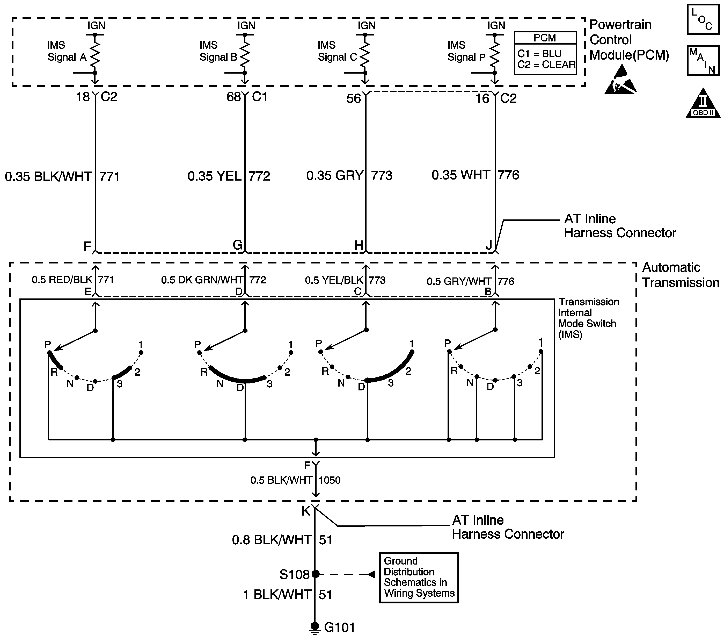
The transmission internal mode switch (IMS) is a sliding contact switch attached to the selector detent inside the transmission side cover. The four inputs to the PCM indicate the position of the transmission range selector. The input voltage level at the PCM is high (B+) when the IMS is open and low when the switch is closed to ground. The four input parameters represented are Signals A, B, C and P (Parity).
If the PCM detects a combination of IMS signals that are invalid, or a transitional state (between gear selector positions), while attempting to start the vehicle, then DTC P1819 sets. DTC P1819 is a type C DTC.
Conditions for Running the DTC
| • | The system voltage is 9-18 volts. |
| • | The ignition switch is in the START position. |
Conditions for Setting the DTC
The PCM detects a combination of IMS signals that are invalid or indicate a transitional state (between gear selector positions) for 0.5 seconds.
Action Taken When the DTC Sets
| • | The PCM does not illuminate the malfunction indicator lamp (MIL). |
| • | The PCM records the operating conditions when the Conditions for Setting the DTC are met. The PCM stores this information as Failure Records. |
| • | The PCM stores DTC P1819 in PCM history. |
Conditions for Clearing the DTC
| • | A scan tool can clear the DTC. |
| • | The PCM clears the DTC from PCM history if the vehicle completes 40 consecutive warm-up cycles without a non-emission-related diagnostic fault occurring. |
| • | The PCM cancels the DTC default actions when the fault no longer exists and the ignition switch is OFF long enough in order to power down the PCM. |
Diagnostic Aids
| • | Inspect the connectors at the controller, the component and all other circuit connecting points for an intermittent condition. Refer to Testing for Intermittent Conditions and Poor Connections in Wiring Systems. |
| • | Inspect the circuit wiring for an intermittent condition. Refer to Testing for Electrical Intermittents in Wiring Systems. |
| • | Refer to the Transmission Internal Mode Switch Logic table for the normal range signals and the invalid combinations. |
Test Description
The numbers below refer to the step numbers on the diagnostic table.
-
HI values for all signals in all ranges indicates the ground circuit is OPEN.
-
If one circuit affects the other, this indicates a short between the two circuits.
-
This step tests the internal transmission harness. If no fault is found in the harness, the fault will be in the switch.
Step | Action | Value(s) | Yes | No |
|---|---|---|---|---|
1 | Did you perform the Powertrain Diagnostic System Check? | -- | Go to Powertrain On Board Diagnostic (OBD) System Check in Engine Controls | |
2 |
Important: Before clearing the DTC, use the Scan Tool in order to record the Freeze Frame and Failure Records. Using the Clear Info function erases the Freeze Frame and Failure Records from the PCM. Does each range selected match the Scan Tool IMS display? | -- | Go to Diagnostic Aids | |
Does the IMS A/B/C/P parameter match the specified value for each range. | HI/HI/HI/HI | |||
4 |
Does the Scan Tool IMS A/B/C/P parameter indicate HI for all range signals? | -- | ||
5 |
Refer to Automatic Transmission Inline Harness Connector End View . Does the voltage measure ignition voltage at all four terminals? | -- | ||
Connect a fused jumper wire from terminal F of the J 44152 (signal circuit A) to ground while monitoring the Scan Tool IMS A/B/C/P parameter. Refer to Automatic Transmission Inline Harness Connector End View . When signal circuit A (CKT 771) is grounded, do any other signal circuits indicate LOW? | -- | |||
7 | Connect a fused jumper wire from terminal G of the J 44152 (signal circuit B) to ground while monitoring the Scan Tool IMS A/B/C/P parameter. Refer to Automatic Transmission Inline Harness Connector End View . When signal circuit B (CKT 772) is grounded, do any other signal circuits indicate LOW? | -- | ||
8 | Connect a fused jumper wire from terminal H of the J 44152 (signal circuit C) to ground while monitoring the Scan Tool IMS A/B/C/P parameter. Refer to Automatic Transmission Inline Harness Connector End View . When signal circuit C (CKT 773) is grounded, do any other signal circuits indicate LOW? | -- | ||
9 | Connect a fused jumper wire from terminal J of the J 44152 (signal circuit P) to ground while monitoring the Scan Tool IMS A/B/C/P parameter. Refer to Automatic Transmission Inline Harness Connector End View . When signal circuit P (CKT 776) is grounded, do any other signal circuits indicate LOW? | -- | ||
10 | Test the signal circuits (CKTs 771, 772, 773 and 776) of the IMS that did not indicate HI for a short to ground between the PCM connector C1 or C2 and the AT Inline 20-way connector. Refer to Circuit Testing and Wiring Repairs in Wiring Systems. Did you find and correct the condition? | -- | ||
11 | Test the signal circuits (CKTs 771, 772, 773 and 776) of the IMS that did not indicate ignition voltage for an open between the PCM connector C1 or C2 and the AT Inline 20-way connector. Refer to Circuit Testing and Wiring Repairs in Wiring Systems. Did you find and correct the condition? | -- | ||
12 | Test the affected signal circuits of the IMS for a shorted together condition between the PCM connector C1 or C2 and the AT Inline 20-way connector. Refer to Circuit Testing and Wiring Repairs in Wiring Systems. Did you find and correct the condition? | -- | ||
Test the signal circuits (CKTs 771, 772, 773 and 776) of the IMS for an open or shorted condition between the AT Inline 20-way connector and the IMS. Refer to Circuit Testing in Wiring Systems. Did you find the condition? | -- | |||
14 | Test the ground circuit (CKT 51) of the IMS for an open between the AT Inline 20-way connector and the chassis. Refer to Circuit Testing and Wiring Repairs in Wiring Systems. Did you find and correct the condition? | -- | ||
15 | Test the ground circuit (CKT 1050) of the IMS for an open between the AT Inline 20-way connector and the IMS. Refer to Circuit Testing in Wiring Systems. Did you find the condition? | -- | ||
16 | Replace the automatic transmission wiring harness assembly. Refer to Solenoids and Wiring Harness Replacement . Did you complete the replacement? | -- | -- | |
17 | Replace the lever assembly-manual shaft detent with internal mode switch. Refer to Transmission Overhaul in the 4T65-E Section of the Transmission Unit Repair Manual. Did you complete the replacement? | -- | -- | |
18 | Replace the PCM. Refer to Powertrain Control Module Replacement/Programming in Engine Controls. Did you complete the replacement? | -- | -- | |
19 | Perform the following procedure in order to verify the repair:
Has the test run and passed? | -- | System OK |
