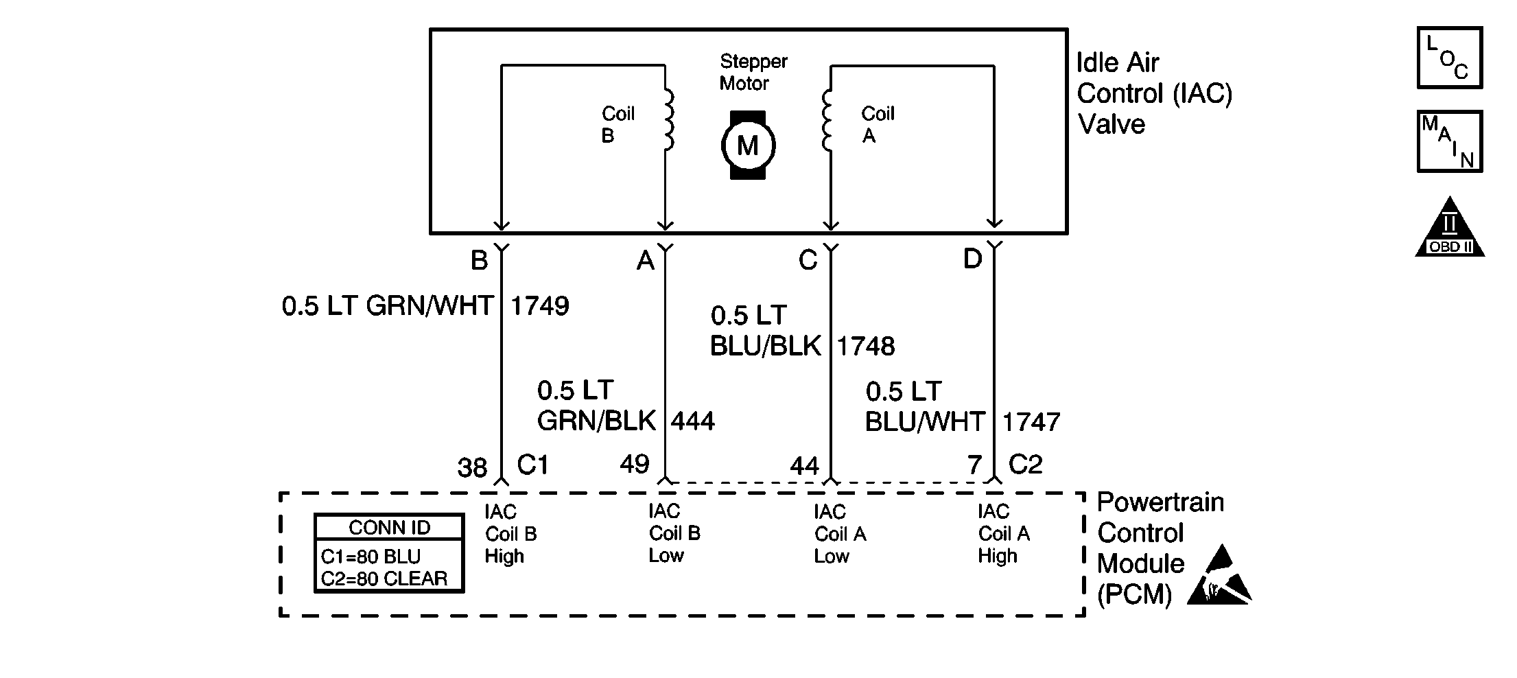
Circuit Description
The PCM controls engine idle speed by adjusting the position of the idle air control (IAC) motor pintle. The IAC is a bi-directional motor driven by two coils. The PCM sends pulses (steps) to the IAC to extend or retract the IAC pintle into a passage in the throttle body to decrease or increase air flow. The commanded IAC position (displayed in counts) can be monitored on the scan tool; a lower number of counts indicates less commanded airflow (pintle extended). This method allows highly accurate control of idle speed and quick response to changes in engine load. If the PCM detects a condition where too high of an idle speed is present and the PCM is unable to adjust idle speed by decreasing the IAC counts, DTC P0507 will set indicating a problem with the idle control system.
Conditions for Running the DTC
| • | No VSS, Evap,TP sensor, misfire, IAT sensor, MAP sensor, fuel trim, fuel injector, EGR, ECT sensor, CKP sensor, or MAF sensor DTCs set. |
| • | Vehicle speed is less than 3 MPH. |
| • | Engine has been running for at least 2 minutes. |
| • | System voltage is between 9-18 volts. |
| • | VIN K -- BARO is more than 65 kPa. |
| • | VIN 1 -- BARO is more than 70 kPa. |
| • | VIN K -- Engine coolant temperature is more than -40°C (-40°F). |
| • | VIN 1 -- Engine coolant temperature is more than 70°C (158°F). |
| • | VIN K -- Intake air temperature is more than -40°C (-40°F). |
| • | VIN 1 -- Intake air temperature is more than -18°C (-4°F). |
| • | VIN K -- The throttle is closed. |
| • | VIN 1 -- The throttle is closed. |
Conditions for Setting the DTC
| • | VIN K -- Engine speed is more than 275 RPM higher than desired Idle (positive idle speed error more than 275 RPM). |
| • | VIN 1 -- Engine speed is more than 275 RPM higher than desired Idle (positive idle speed error more than 275 RPM). |
| • | Above conditions for more than 15 seconds. |
Action Taken When the DTC Sets
| • | The PCM illuminates the malfunction indicator lamp (MIL) on the second consecutive ignition cycle that the diagnostic runs and fails. |
| • | The PCM records the operating conditions at the time the diagnostic fails. The first time the diagnostic fails, the PCM stores this information in the Failure Records. If the diagnostic reports a failure on the second consecutive ignition cycle, the PCM records the operating conditions at the time of the failure. |
| • | The PCM writes the conditions to the Freeze Frame and updates the Failure Records. |
Conditions for Clearing the MIL/DTC
| • | The PCM will turn OFF the malfunction indicator lamp (MIL) during the third consecutive trip in which the diagnostic has run and passed. |
| • | The history DTC will clear after 40 consecutive warm-up cycles have occurred without a malfunction. |
| • | The DTC can be cleared by using a scan tool. |
Diagnostic Aids
Check for the following conditions:
| • | Poor connection at PCM or IAC motor. Inspect harness connectors for backed out terminals, improper mating, broken locks, improperly formed or damaged terminals, and poor terminal to wire connection. |
| • | Damaged harness. Inspect the wiring harness for damage. |
| • | Vacuum leak. Check for a condition that causes a vacuum leak, such as disconnected or damaged hoses, leaks at EGR valve and EGR pipe to intake manifold, leaks at throttle body, malfunctioning or incorrectly installed PCV valve, leaks at intake manifold, etc. |
| • | Throttle body. Check for a sticking throttle plate. Also inspect the IAC passage for deposits or objects which will not allow the IAC pintle to fully extend. |
Reviewing the Failure Records vehicle mileage since the diagnostic test last failed may help determine how often the condition that caused the DTC to be set occurs. This may assist in diagnosing the condition.
Test Description
The number below refer to the step number on the diagnostic table.
Step | Action | Values | Yes | No | ||||||||||
|---|---|---|---|---|---|---|---|---|---|---|---|---|---|---|
1 | Did you perform the Powertrain On-Board Diagnostic System Check ? | -- | ||||||||||||
2 | Are any other DTCs set? | -- | Go to applicable DTC | |||||||||||
3 |
Does engine speed vary less than the specified value from each RPM command? | 100 RPM | Go to Diagnostic Aids | |||||||||||
4 |
Does each node light cycle red and green (never OFF)? | -- | ||||||||||||
5 |
Was a problem found? | -- | ||||||||||||
6 |
Was a problem found? | -- | ||||||||||||
7 |
Was a problem found? | -- | ||||||||||||
8 | Replace the IAC valve. Refer to Idle Air Control Valve Replacement . Is action complete? | -- | -- | |||||||||||
9 |
Was a problem found? | -- | ||||||||||||
|
Important:: The replacement PCM must be programmed. Replace the PCM. Refer to Powertrain Control Module Replacement/Programming . Is action complete? | -- | -- | ||||||||||||
11 |
Does engine speed vary less than the specified value from each RPM command? | 100 RPM | System OK |
