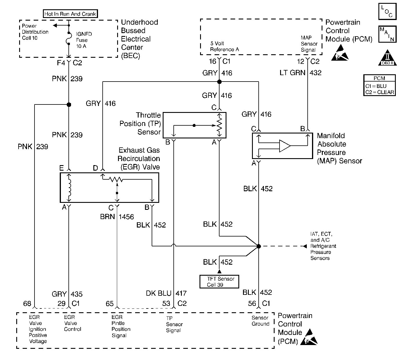
Circuit Description
The PCM uses the 5 Volt Reference A circuit as a sensor feed to the following sensors:
| • | The TP sensor. |
| • | The MAP sensor. |
| • | The EGR valve pintle position sensor. |
| • | The engine oil pressure sensor. |
The PCM monitors the voltage on the 5 Volt Reference A circuit. If the voltage is out of tolerance, the PCM will set DTC P1635.
Conditions for Setting the DTC
| • | The PCM detects a voltage out of tolerance condition on the 5 Volt Reference A circuit. |
| • | The above condition is present for longer than 19 seconds. |
Action Taken When the DTC Sets
| • | The PCM will illuminate the malfunction indicator lamp (MIL) during the second consecutive trip in which the diagnostic test has been run and failed. |
| • | The PCM will store conditions which were present when the DTC set as Freeze Frame and Failure Records data. |
Conditions for Clearing the MIL/DTC
| • | The PCM will turn OFF the MIL during the third consecutive trip in which the diagnostic has been run and passed. |
| • | The History DTC will clear after 40 consecutive warm-up cycles have occurred without a malfunction. |
| • | The DTC can be cleared by using the scan tool. |
Diagnostic Aids
Important:: Be sure to inspect PCM and engine grounds for being secure and clean.
Check for the following conditions:
| • | Poor connection at the PCM. |
| Inspect harness connectors for backed out terminals, improper mating, broken locks, improperly formed or damaged terminals, and poor terminal to wire connection. |
| • | Damaged harness. |
| Inspect the wiring harness for damage. |
| • | If the harness appears to be OK, observe the MAP display on the scan tool with the ignition ON, engine not running while moving connectors and wiring harnesses related to the following sensors. A change in the MAP display will indicate the location of the malfunction. |
| - | The TP sensor. |
| - | The MAP sensor. |
| - | The EGR valve. |
| - | The engine oil pressure sensor. |
Reviewing the Fail Records vehicle mileage since the diagnostic test last failed may help determine how often the condition that caused the DTC to be set occurs. This may assist in diagnosing the condition.
Test Description
Number(s) below refer to the step number(s) on the Diagnostic Table.
-
A malfunctioning EGR valve can leak a small amount of current from the ignition feed circuit to the 5 volt reference A circuit. If the problem does not exist with the EGR valve disconnected, replace the EGR valve.
-
This vehicle is equipped with a PCM which utilizes an Electrically Erasable Programmable Read Only Memory (EEPROM). When the PCM is being replaced, the new PCM must be programmed.
Step | Action | Value(s) | Yes | No | ||||||||
|---|---|---|---|---|---|---|---|---|---|---|---|---|
1 | Was the Powertrain On-Board Diagnostic (OBD) System Check performed? | -- | ||||||||||
2 |
Was a problem found? | -- | ||||||||||
3 | Select DTC info, Last Tst Fail and record any other DTCs set. Are any of the following DTCs set? | -- | Diagnose the other DTC first | |||||||||
4 |
Is voltage greater than the specified value indicated? | 5.5V | ||||||||||
Monitor the digital multimeter connected between the 5 volt reference A circuit and the PCM ground circuit while disconnecting the EGR valve. Is voltage greater than the specified value still indicated with the EGR valve disconnected? | 5.5V | |||||||||||
6 |
Was a problem found? | -- | ||||||||||
7 |
Was a problem found? | -- | ||||||||||
8 | Replace the EGR valve. Refer to Exhaust Gas Recirculation Valve Replacement . Is action complete? | -- | -- | |||||||||
9 |
Is voltage less than the specified value indicated? | 4.5 V | ||||||||||
10 |
Refer to Manifold Absolute Pressure Sensor Replacement . Refer to Manifold Absolute Pressure Sensor Replacement . Refer to Exhaust Gas Recirculation Valve Replacement . Refer to Engine Oil Pressure Sensor . Was a problem found? | -- | ||||||||||
11 |
Was a problem found? | -- | ||||||||||
12 |
Was a problem found? | -- | ||||||||||
Replace PCM. Important:: The replacement PCM must be programmed. Refer to Powertrain Control Module Replacement/Programming . Is action complete? | -- | -- | ||||||||||
14 |
Does the scan tool indicate DTC P1635 failed this ign? | -- | System OK |
