Removal Procedure
Notice:
• Remove the fuel rail assembly carefully in order to prevent damage
to the injector electrical connector terminals and the injector spray tips.
Support the fuel rail after the fuel rail is removed in order to avoid damaging
the fuel rail components. • Cap the fittings and plug the holes when servicing the fuel system
in order to prevent dirt and other contaminants from entering open pipes and
passages.
- Relieve the fuel system pressure. Refer to the Fuel Pressure Relief .
- Clean the fuel rail assembly with a spray type engine cleaner, GM X-30A or equivalent, if necessary. Follow the package instructions. Do not soak the fuel rail in liquid cleaning solvent.
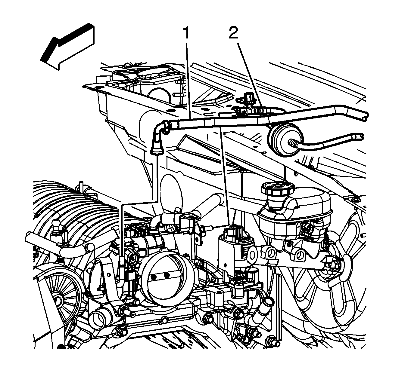
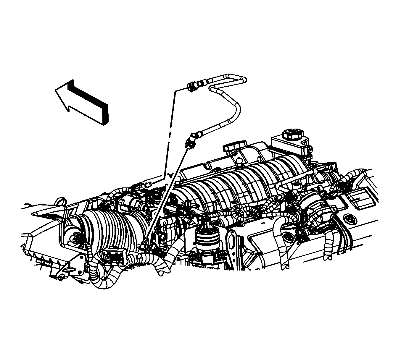
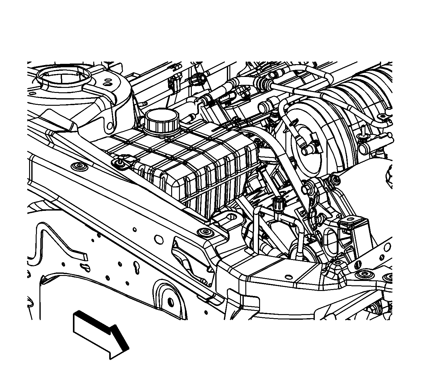
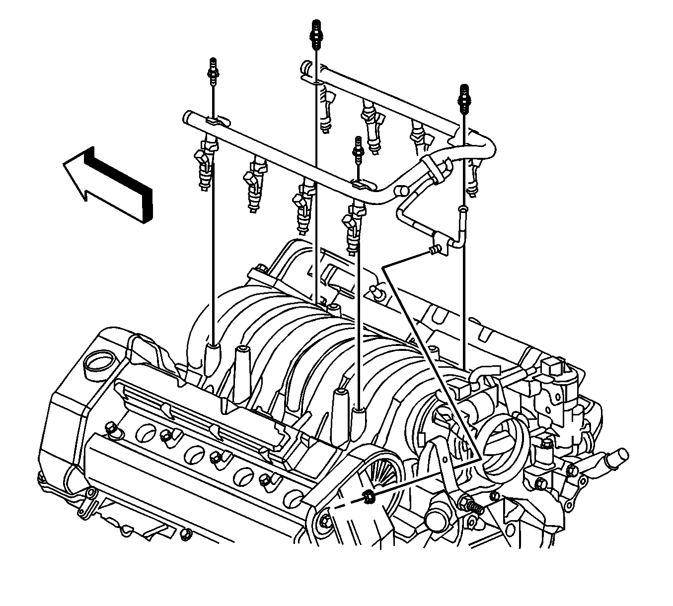
- Disconnect the fuel feed pipe quick connect fitting (1) from the fuel rail. Refer to Metal Collar Quick Connect Fitting Service .
- Disconnect the positive crankcase ventilation (PCV) air tube quick connect fitting from the camshaft cover. Refer to Plastic Collar Quick Connect Fitting Service .
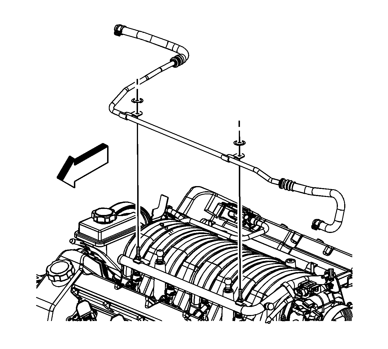
- Reposition the surge tank inlet pipe hose clamp at the surge tank.
- Remove the surge tank inlet pipe hose from the surge tank.
- Reposition the surge tank inlet pipe hose clamp at the engine fitting.
- Remove the surge tank inlet pipe hose from the engine fitting.
- Remove the surge tank inlet pipe nuts.
- Remove the surge tank inlet pipe from the fuel rail studs.
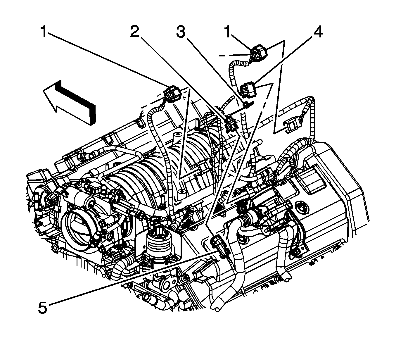
- Disconnect the engine harness electrical connector (1) from the starter solenoid cable electrical connector.
- Disconnect the engine harness electrical connectors (3) from the front fuel injectors.
- Disconnect the engine harness electrical connectors (1) from the rear fuel injectors.
- Remove the engine harness clip (2) from the fuel rail stud.
- Lay the harness aside.
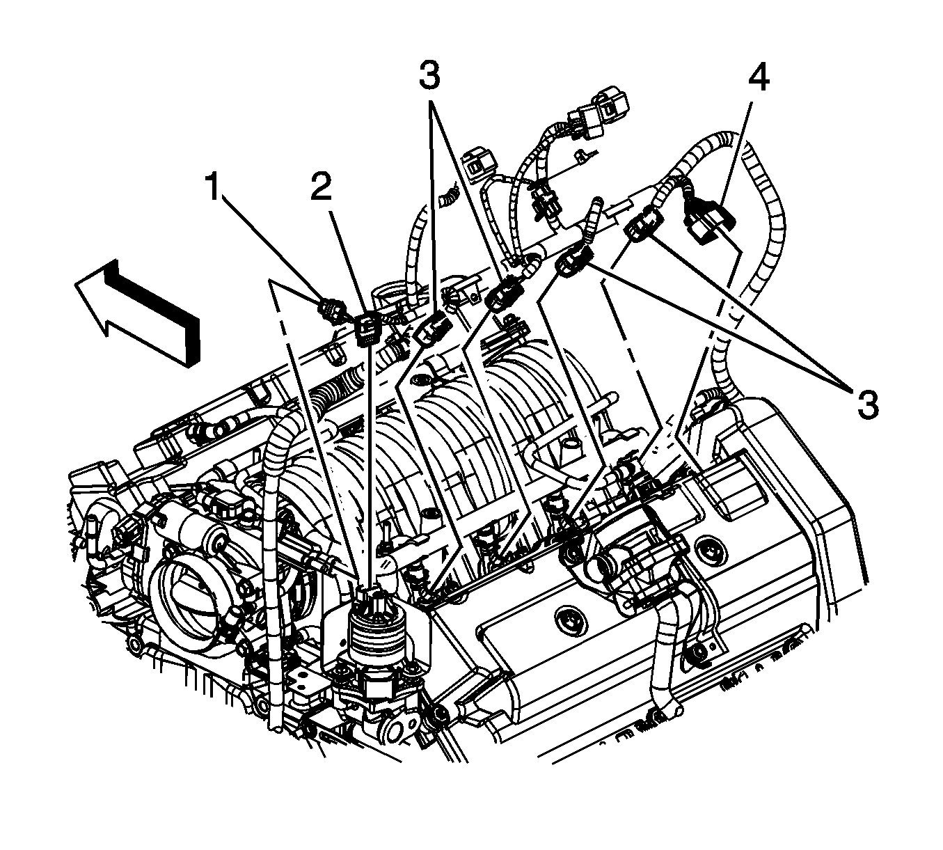
- Remove the fuel rail bracket retainer nut (2).
- Remove the fuel rail studs (1).
- Remove the fuel rail.
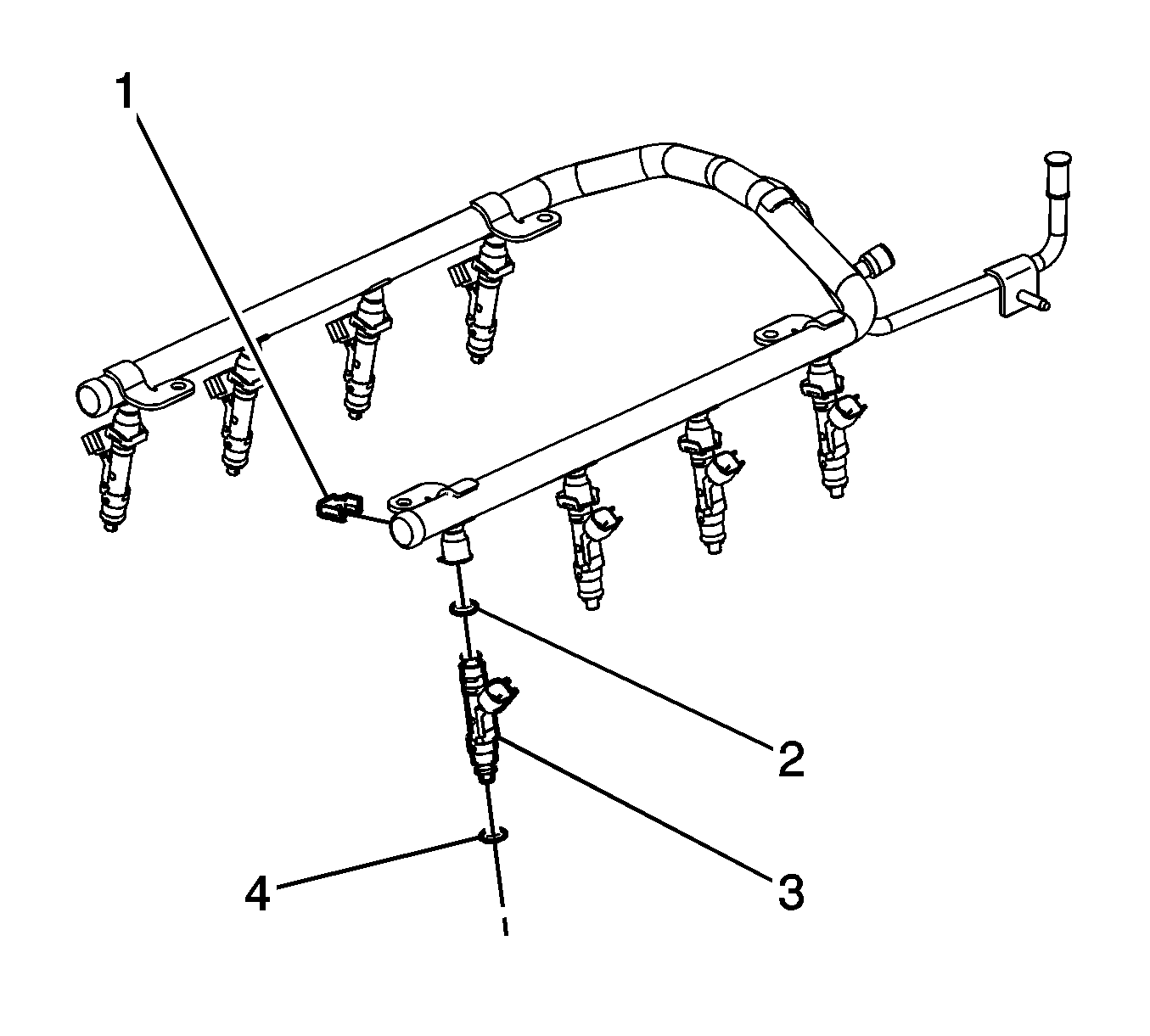
- Remove and discard the O-ring seals (4) from the spray tip end of each fuel injector.
- If replacing the fuel rail, remove the fuel injectors. Refer to Fuel Injector Replacement .
Installation Procedure
Notice:
• Use care when servicing the fuel system components, especially
the fuel injector electrical connectors, the fuel injector tips, and
the injector O-rings. Plug the inlet and the outlet ports of the fuel rail
in order to prevent contamination. • Do not use compressed air to clean the fuel rail assembly as this
may damage the fuel rail components. • Do not immerse the fuel rail assembly in a solvent bath in order
to prevent damage to the fuel rail assembly.
- If the fuel rail was replaced, install the fuel injectors. Refer to Fuel Injector Replacement .
- Install NEW O-ring seals (4) to the spray tip end of each fuel injector.
- Lubricate the NEW lower injector O-ring seals with clean engine oil.
- Install the fuel rail.
- Install the fuel rail studs (1).
- Install the fuel rail bracket retainer nut (2).
- Position the harness over the engine.
- Install the engine harness clip (2) to the fuel rail stud.
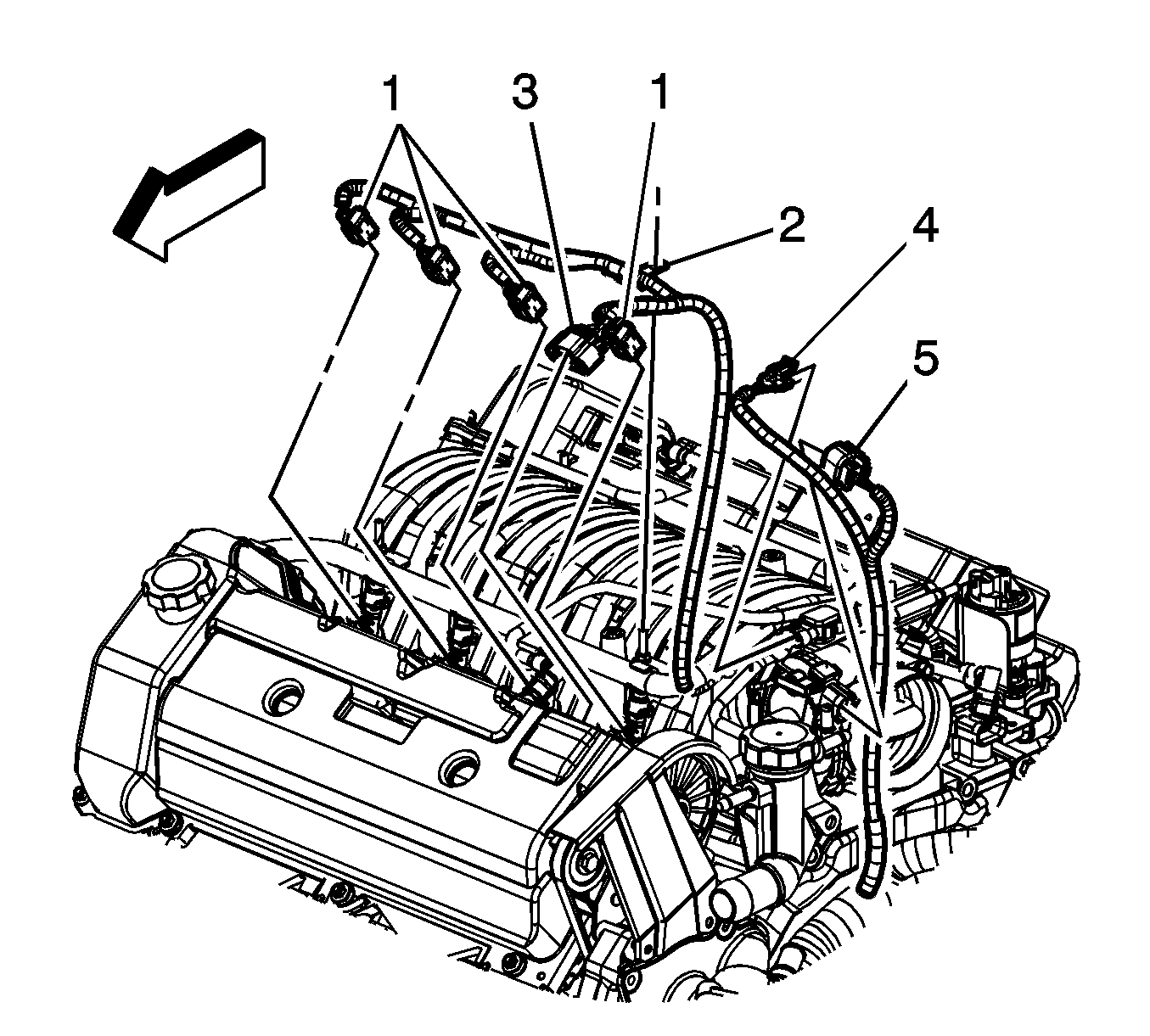
- Connect the engine harness electrical connectors (1) to the rear fuel injectors.
- Connect the engine harness electrical connectors (3) to the front fuel injectors.
- Connect the engine harness electrical connector (1) to the starter solenoid cable electrical connector.
- Install the surge tank inlet pipe to the fuel rail studs.
- Install the surge tank inlet pipe nuts.
- Install the surge tank inlet pipe hose to the engine fitting.
- Position the surge tank inlet pipe hose clamp at the engine fitting.
- Install the surge tank inlet pipe hose to the surge tank.
- Position the surge tank inlet pipe hose clamp at the surge tank.
- Connect the PCV air tube quick connect fitting to the camshaft cover. Refer to Plastic Collar Quick Connect Fitting Service .
- Connect the fuel feed pipe quick connect fitting (1) to the fuel rail. Refer to Metal Collar Quick Connect Fitting Service .
- Connect the negative battery cable. Refer to Battery Negative Cable Disconnection and Connection .
- Inspect for fuel leaks using the following procedures:
- Install the fuel injector sight shield. Refer to Fuel Injector Sight Shield Replacement .
Notice: Refer to Fastener Notice in the Preface section.
Tighten
Tighten the studs to 10 N·m (89 lb in).
Tighten
Tighten the nut to 10 N·m (89 lb in).
| 21.1. | Turn ON the ignition, with the engine OFF for 2 seconds. |
| 21.2. | Turn OFF the ignition for 10 seconds. |
| 21.3. | Turn ON the ignition, with the engine OFF. |
| 21.4. | Inspect for fuel leaks. |
