Exhaust Manifold Replacement - Right Side w/o NC8
Removal Procedure
Caution: In order to avoid being burned, do not service the exhaust system while it is still hot. Service the system when it is cool.
Caution: Always wear protective goggles and gloves when removing exhaust parts as falling rust and sharp edges from worn exhaust components could result in serious personal injury.
- Remove the fuel injector sight shield. Refer to Fuel Injector Sight Shield Replacement in Engine Mechanical - 3.8L.
- Disconnect the heated oxygen sensor at the sensor pigtail.
- Remove the right side spark plugs. Refer to Spark Plug Replacement in Engine Controls - 3.8L.
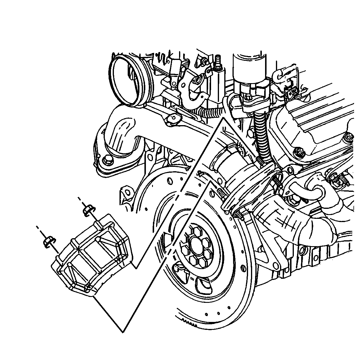
- Remove the two nuts securing the power brake booster heat shield to the exhaust crossover.
- Remove the power brake booster heat shield from the exhaust crossover.
- Remove the two bolts attaching the exhaust crossover to the right exhaust manifold.
- Remove the transaxle filler tube. Refer to Transmission Fluid Filler Tube and Seal Replacement in Automatic Transaxle - 4T65-E.
- Raise and support the vehicle. Refer to Lifting and Jacking the Vehicle in General Information.
- Remove the exhaust manifold pipe. Refer to Exhaust Manifold Pipe Replacement .
- Remove the heated oxygen sensor if replacement is necessary. Refer to Heated Oxygen Sensor 1 Replacement in Engine Controls - 3.8L.
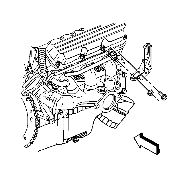
- Remove the fuel injector sight shield bracket retaining nuts.
- Remove the fuel injector sight shield bracket.
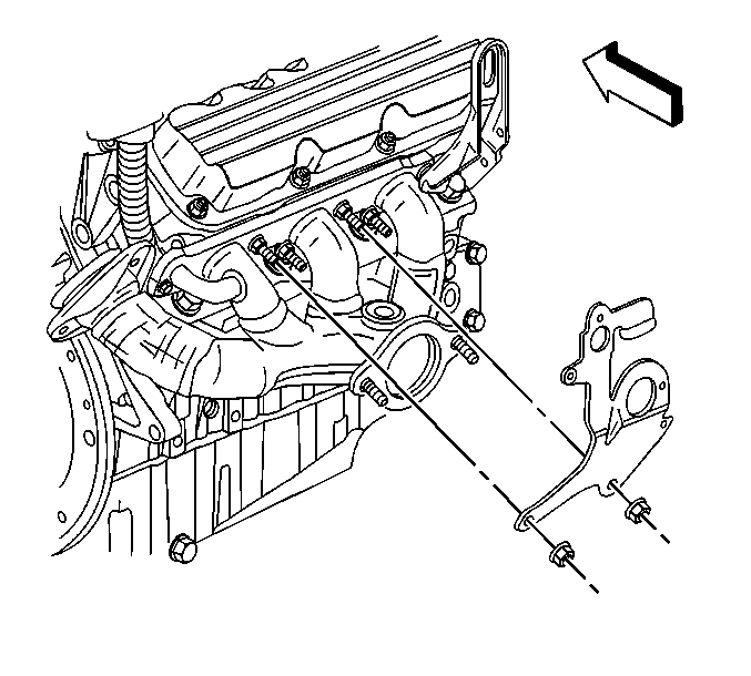
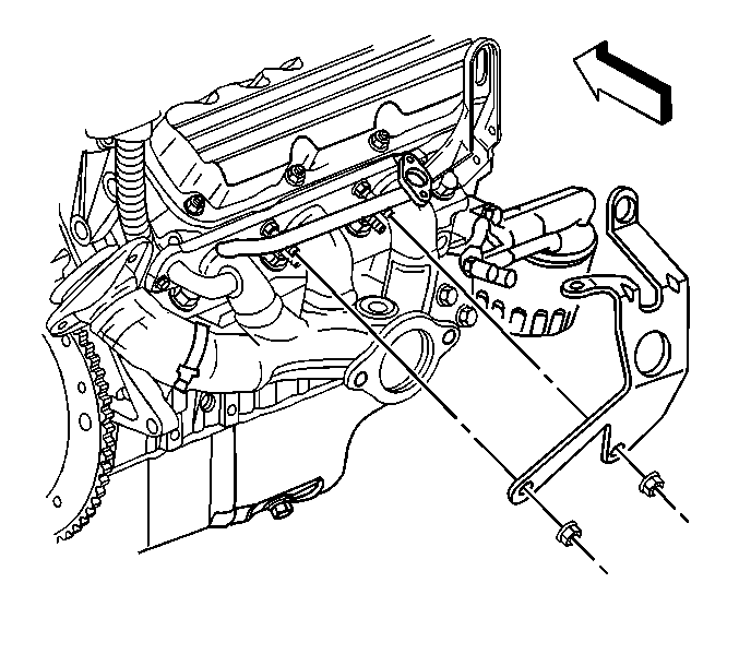
- Remove the right engine lift bracket retaining fasteners.
- Remove the right engine lift bracket.
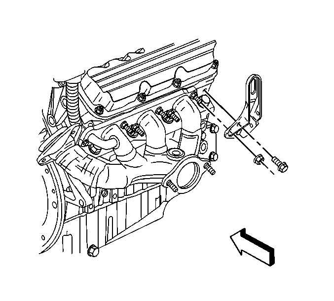
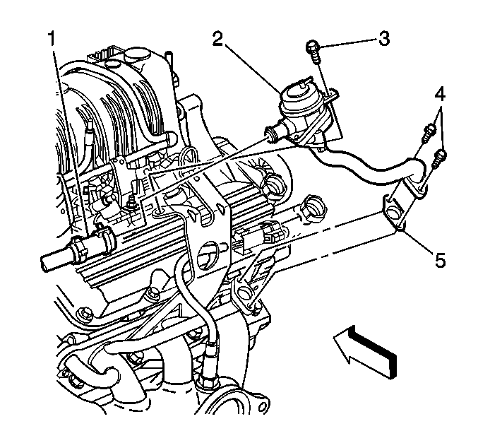
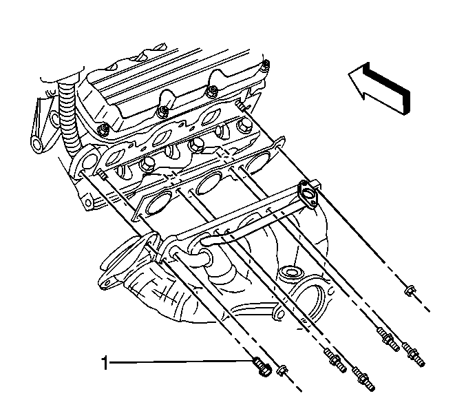
- Remove the bolt (1) securing the EGR inlet pipe to the right exhaust manifold.
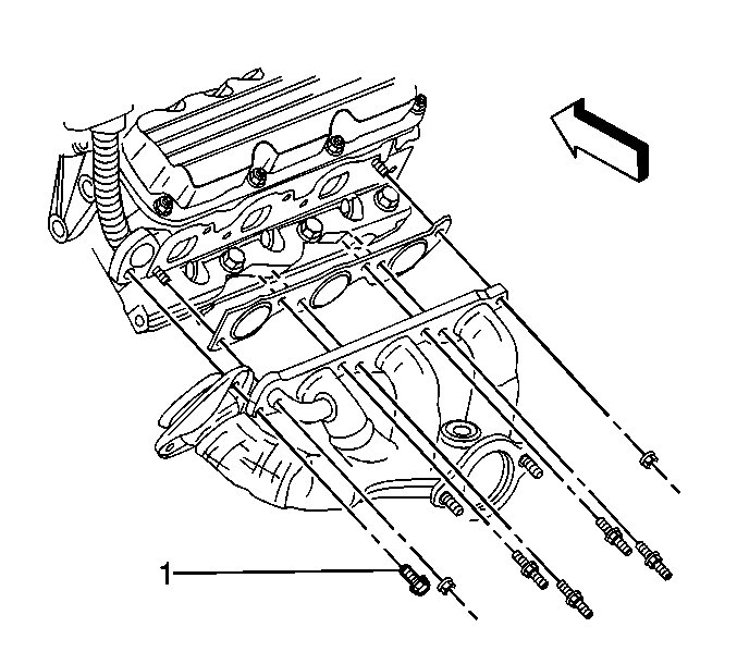
- Remove the right exhaust manifold retaining fasteners.
- Remove the right exhaust manifold and the gasket from the engine. Do not reuse the gasket.
- Remove the exhaust crossover seal from the exhaust crossover. Do not reuse the seal.
- Clean and inspect the right exhaust manifold. Refer to Exhaust Manifold Cleaning and Inspection in Engine Mechanical - 3.8L Unit Repair.
Installation Procedure
- Place a NEW exhaust crossover seal over the exhaust crossover.
- Place a NEW exhaust manifold gasket over the cylinder head studs.
- Position the right exhaust manifold around the exhaust crossover and up to the right cylinder head.
- Install the right exhaust manifold fasteners.
- Install the bolt (1) securing the EGR inlet pipe to the right exhaust manifold.
- Position the right engine lift bracket to the engine.
- Install the right engine lift bracket retaining fasteners.
- Position the fuel injector sight shield bracket to the engine.
- Install the fuel injector sight shield bracket retaining nuts.
- Install the heated oxygen sensor. Refer to Heated Oxygen Sensor 1 Replacement in Engine Controls - 3.8L.
- Install the exhaust manifold pipe. Refer to Exhaust Manifold Pipe Replacement .
- Lower the vehicle.
- Install the transaxle filler tube. Refer to Transmission Fluid Filler Tube and Seal Replacement in Automatic Transaxle - 4T65-E.
- Install the bolts securing the exhaust crossover to the right exhaust manifold.
- Install the power brake booster heat shield to the exhaust crossover.
- Install the two nuts securing the power brake booster heat shield to the exhaust crossover.
- Install the right side spark plugs. Refer to Spark Plug Replacement in Engine Controls - 3.8L.
- Connect the heated oxygen sensor at the sensor pigtail.
- Install the fuel injector sight shield. Refer to Fuel Injector Sight Shield Replacement in Engine Mechanical - 3.8L.
Notice: Use the correct fastener in the correct location. Replacement fasteners must be the correct part number for that application. Fasteners requiring replacement or fasteners requiring the use of thread locking compound or sealant are identified in the service procedure. Do not use paints, lubricants, or corrosion inhibitors on fasteners or fastener joint surfaces unless specified. These coatings affect fastener torque and joint clamping force and may damage the fastener. Use the correct tightening sequence and specifications when installing fasteners in order to avoid damage to parts and systems.
Tighten
Tighten the exhaust manifold fasteners to 30 N·m (22 lb ft).
Tighten
Tighten the EGR inlet pipe bolt to 30 N·m (22 lb ft).
Tighten
Tighten the engine lift bracket retaining fasteners to 30 N·m (22 lb ft).
Tighten
Tighten the fuel injector sight shield bracket retaining nuts to 30 N·m (22 lb ft).
Tighten
Tighten the exhaust crossover bolts to 20 N·m (15 lb ft).
Tighten
Tighten the power brake booster heat shield nuts to 20 N·m (15 lb ft).
Exhaust Manifold Replacement - Right Side w/NC8
Removal Procedure
Caution: In order to avoid being burned, do not service the exhaust system while it is still hot. Service the system when it is cool.
Caution: Always wear protective goggles and gloves when removing exhaust parts as falling rust and sharp edges from worn exhaust components could result in serious personal injury.
- Remove the fuel injector sight shield. Refer to Fuel Injector Sight Shield Replacement in Engine Mechanical - 3.8L.
- Disconnect the heated oxygen sensor at the sensor pigtail.
- Remove the right side spark plugs. Refer to Spark Plug Replacement in Engine Controls - 3.8 L.
- Disconnect the connector from the secondary AIR valve (2).
- Disconnect the hose (1) from the secondary AIR valve (2).
- Remove the two bolts (4) attaching the secondary AIR tube to the exhaust manifold.
- Remove the secondary AIR tube and the gasket (5) from the exhaust manifold. Do not reuse the gasket.
- Remove the bolt (3) securing the secondary AIR valve (2) to the fuel injector sight shield bracket.
- Remove the secondary AIR valve (2) from the fuel injector sight shield bracket.
- Remove the two nuts securing the power brake booster heat shield to the exhaust crossover.
- Remove the power brake booster heat shield from the exhaust crossover.
- Remove the two bolts attaching the exhaust crossover to the right exhaust manifold.
- Remove the transaxle filler tube. Refer to Transmission Fluid Filler Tube and Seal Replacement in Automatic Transaxle - 4T65-E.
- Raise and support the vehicle. Refer to Lifting and Jacking the Vehicle in General Information.
- Remove the exhaust manifold pipe. Refer to Exhaust Manifold Pipe Replacement .
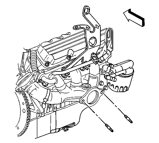
- Remove the right exhaust manifold studs.
- Remove the heated oxygen sensor if replacement is necessary. Refer to Heated Oxygen Sensor 1 Replacement in Engine Controls - 3.8L.
- Remove the fuel injector sight shield bracket retaining nuts.
- Remove the fuel injector sight shield bracket.
- Remove the right engine lift bracket retaining fasteners.
- Remove the right engine lift bracket.
- Remove the bolt (1) securing the EGR inlet pipe to the right exhaust manifold.
- Remove the right exhaust manifold retaining fasteners.
- Remove the right exhaust manifold and the gasket from the engine. Do not reuse the gasket.
- Remove the exhaust crossover seal from the exhaust crossover. Do not reuse the seal.
- Clean and inspect the right exhaust manifold. Refer to Exhaust Manifold Cleaning and Inspection in Engine Mechanical - 3.8L Unit Repair.
Installation Procedure
- Place a NEW exhaust crossover seal over the exhaust crossover.
- Place a NEW exhaust manifold gasket over the cylinder head studs.
- Position the right exhaust manifold around the exhaust crossover and up to the right cylinder head.
- Install the right exhaust manifold fasteners.
- Install the bolt (1) securing the EGR inlet pipe to the right exhaust manifold.
- Position the right engine lift bracket to the engine.
- Install the right engine lift bracket retaining fasteners.
- Position the fuel injector sight shield bracket to the engine.
- Install the fuel injector sight shield bracket retaining nuts.
- Install the right exhaust manifold studs.
- Install the heated oxygen sensor. Refer to Heated Oxygen Sensor 1 Replacement in Engine Controls - 3.8L.
- Install the exhaust manifold pipe. Refer to Exhaust Manifold Pipe Replacement .
- Lower the vehicle.
- Install the transaxle filler tube. Refer to Transmission Fluid Filler Tube and Seal Replacement in Automatic Transaxle - 4T65-E.
- Install the bolts securing the exhaust crossover to the right exhaust manifold.
- Install the power brake booster heat shield to the exhaust crossover.
- Install the two nuts securing the power brake booster heat shield to the exhaust crossover.
- Position the secondary AIR valve (2) to the fuel injector sight shield bracket.
- Install the bolt (3) securing the secondary AIR valve (2) to the fuel injector sight shield bracket.
- Install the new gasket (5) to the secondary AIR tube.
- Install the two bolts (4) attaching the secondary AIR tube to the exhaust manifold.
- Connect the hose (1) to the secondary AIR valve (2).
- Connect the connector to the secondary AIR valve (2).
- Install the right side spark plugs. Refer to Spark Plug Replacement in Engine Controls - 3.8L.
- Connect the heated oxygen sensor at the sensor pigtail.
- Install the fuel injector sight shield. Refer to Fuel Injector Sight Shield Replacement in Engine Mechanical - 3.8L.
Notice: Use the correct fastener in the correct location. Replacement fasteners must be the correct part number for that application. Fasteners requiring replacement or fasteners requiring the use of thread locking compound or sealant are identified in the service procedure. Do not use paints, lubricants, or corrosion inhibitors on fasteners or fastener joint surfaces unless specified. These coatings affect fastener torque and joint clamping force and may damage the fastener. Use the correct tightening sequence and specifications when installing fasteners in order to avoid damage to parts and systems.
Tighten
Tighten the exhaust manifold fasteners to 30 N·m (22 lb ft).
Tighten
Tighten the EGR inlet pipe bolt to 30 N·m (22 lb ft).
Tighten
Tighten the engine lift bracket retaining fasteners to 30 N·m (22 lb ft).
Tighten
Tighten the fuel injector sight shield bracket retaining nuts to 30 N·m (22 lb ft).
Tighten
Tighten the exhaust manifold studs to 9 N·m (80 lb in).
Tighten
Tighten the exhaust crossover bolts to 20 N·m (15 lb ft).
Tighten
Tighten the power brake booster heat shield nuts to 20 N·m (15 lb ft).
Tighten
Tighten the secondary AIR valve bolt to 25 N·m (18 lb ft).
Tighten
Tighten the secondary AIR tube bolts to 10 N·m (89 lb in).
