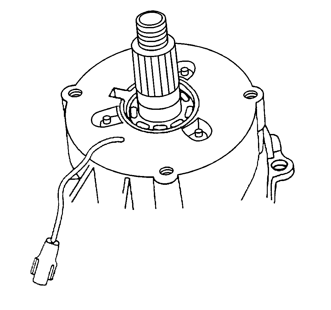
- Install the needle bearings
to the mainshaft.
- Install the retainer ring with the numbered side of the bearing
facing the bearing driver.
- Install the oil pump pickup to the pickup tube.
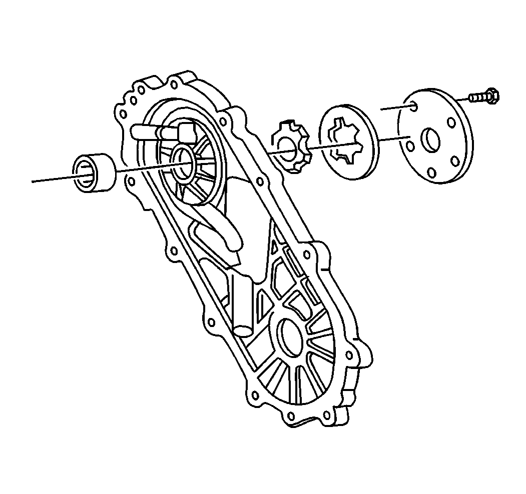
- Install the following components to the oil pump body:
- Lubricate the assembly with automatic transmission fluid.
Use Dexron® III automatic transmission fluid or equivalent.
Notice: Use the correct fastener in the correct location. Replacement fasteners
must be the correct part number for that application. Fasteners requiring
replacement or fasteners requiring the use of thread locking compound or sealant
are identified in the service procedure. Do not use paints, lubricants, or
corrosion inhibitors on fasteners or fastener joint surfaces unless specified.
These coatings affect fastener torque and joint clamping force and may damage
the fastener. Use the correct tightening sequence and specifications when
installing fasteners in order to avoid damage to parts and systems.
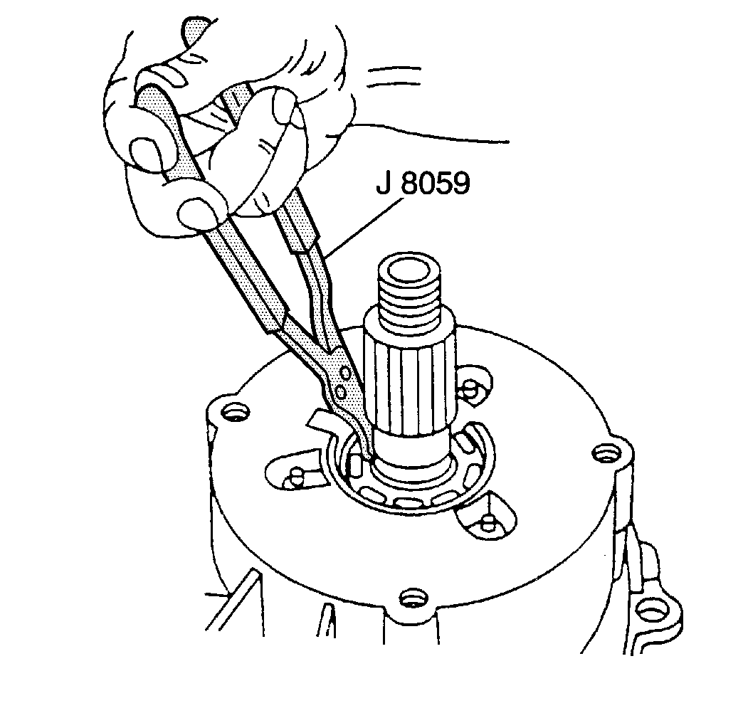
- Install the oil pump
drive gear and the oil pump driven gear into the oil pump body.
Tighten
Tighten the pump cover bolts to 10 N·m (89 lb in).
- Inspect the oil pump operation on the mainshaft.
The mainshaft must turn freely within the oil pump.
If binding occurs, adjust the mainshaft:
| 7.3. | Reinstall the cover. |
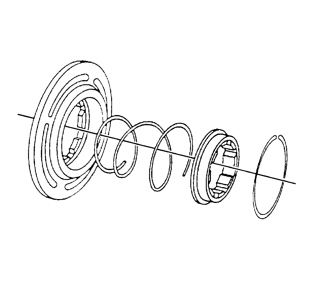
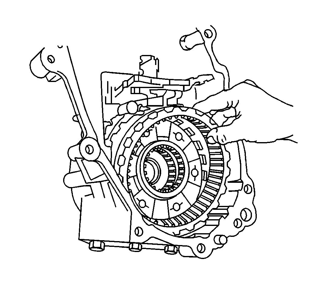
- Install the compression
spring to the lockup collar.
- Install the lockup hub which compresses the compression spring.
- Install the synchronizer hub snap ring.
- Use the J 37668
in
order to install the rear output shaft seal to the rear bearing retainer.
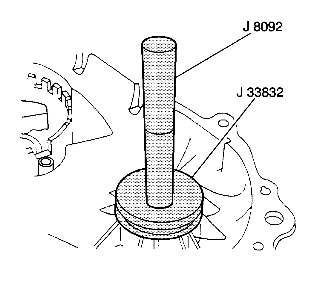
- Use the J 8092
and the J 33832
in order to install the front output bearing to the front
case.
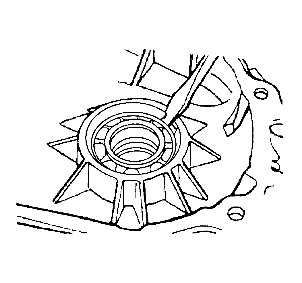
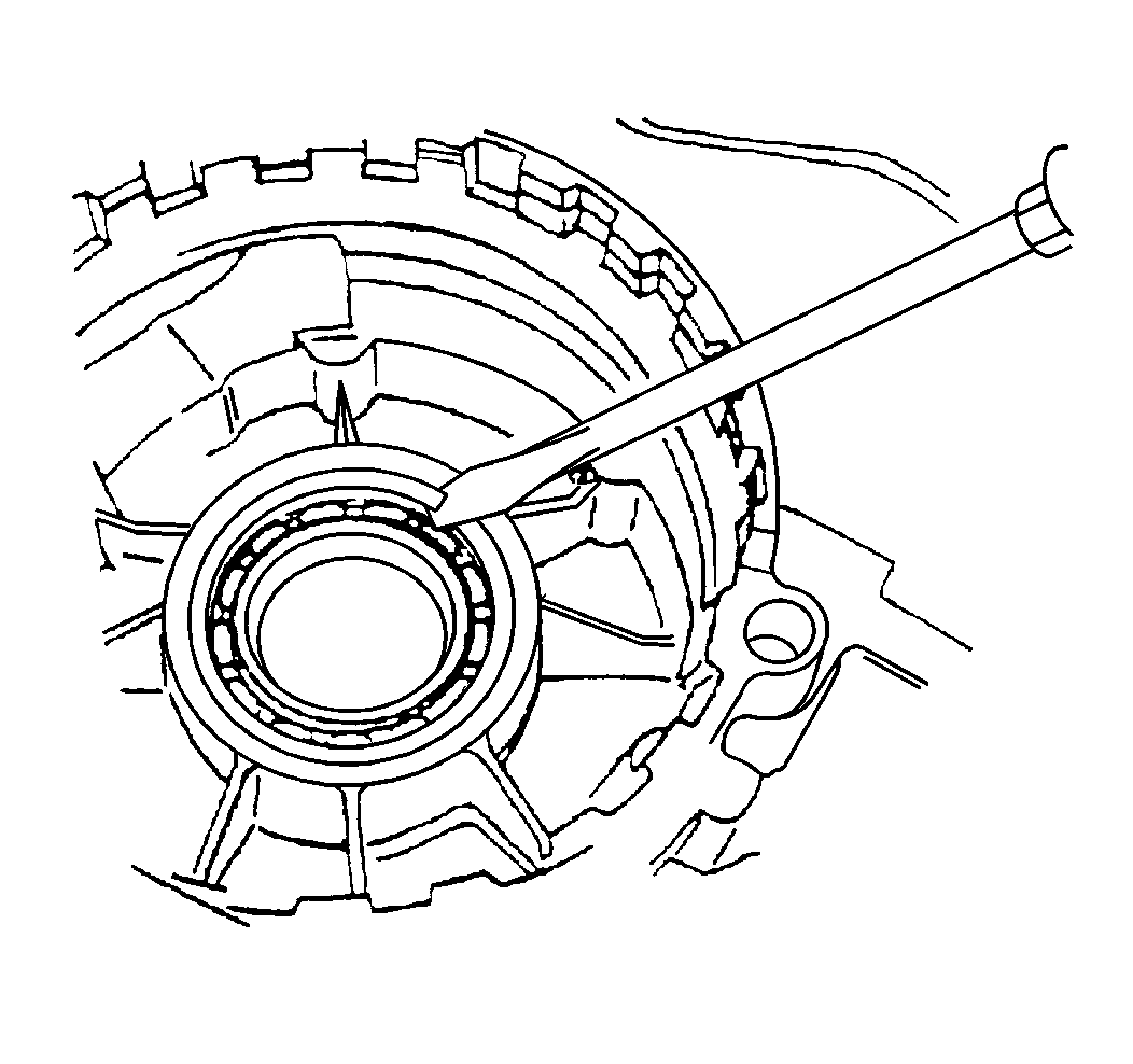
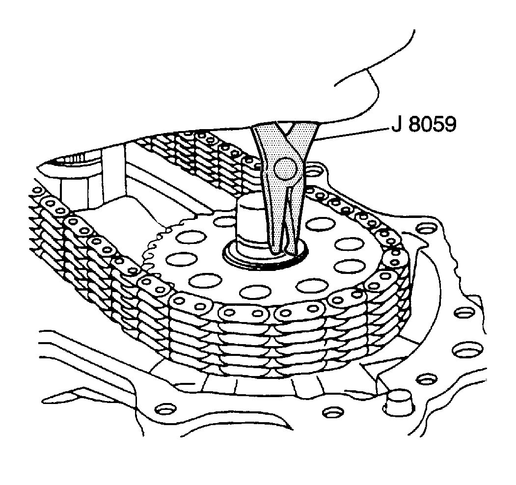
- Install the front output
bearing snap ring to the front case.
- Use the J 37668
in
order to install the front output shaft seal to the front case.
- Use the J 8092
and
the J 33832
in order to
install the rear output bearing to the rear case.
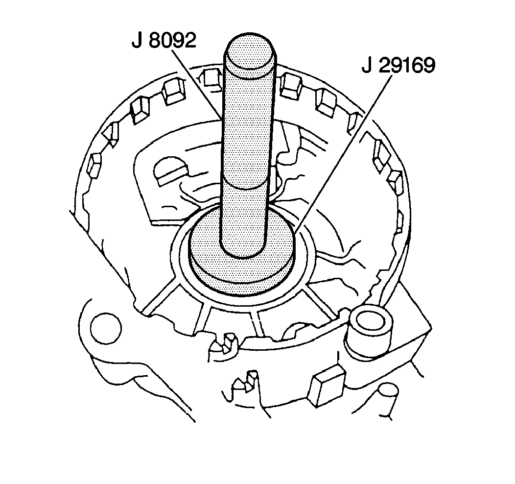
- Use the J 8092
and the J 29169
in order to install the front input bearing to the front
case.
- Install the front input
bearing snap ring to the front case.
- Install the following
components to the front case:
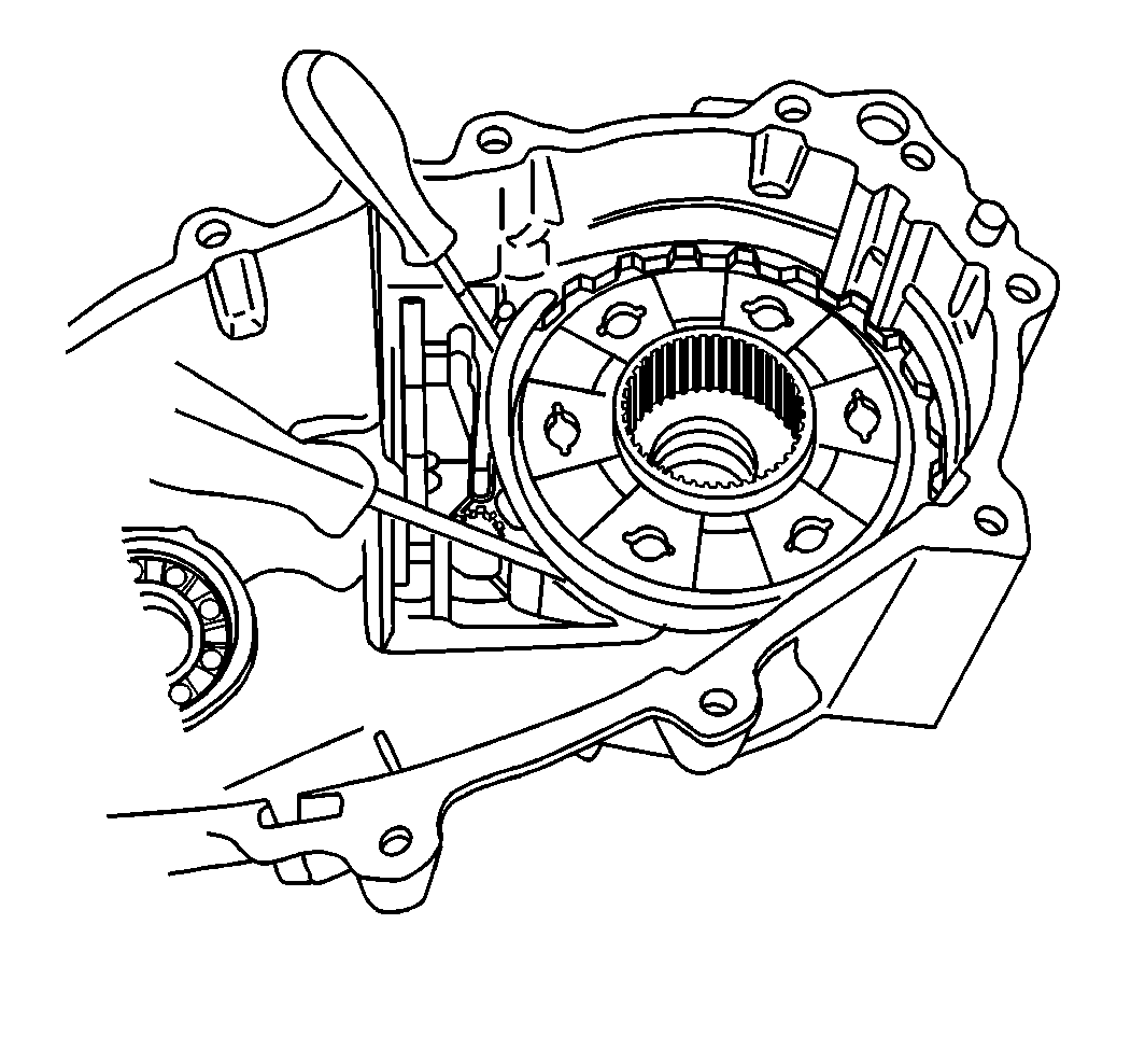
- Install the selector shaft through the case.
Align the selector shaft with the spline on the selector.
- Connect the retainer clip to the selector shaft.

- Install the power take
off drive gear facing the planetary gears and the input assembly to the front
case.
- Install the input carrier
snap ring to the input carrier.
- Use the J 37668
in
order to install the input shaft front oil seal to the front case.
- Install the annulus gear
to the front case.
- Install the annulus gear
snap ring to the front case. The open end of the snap ring should be facing
the shift shaft.
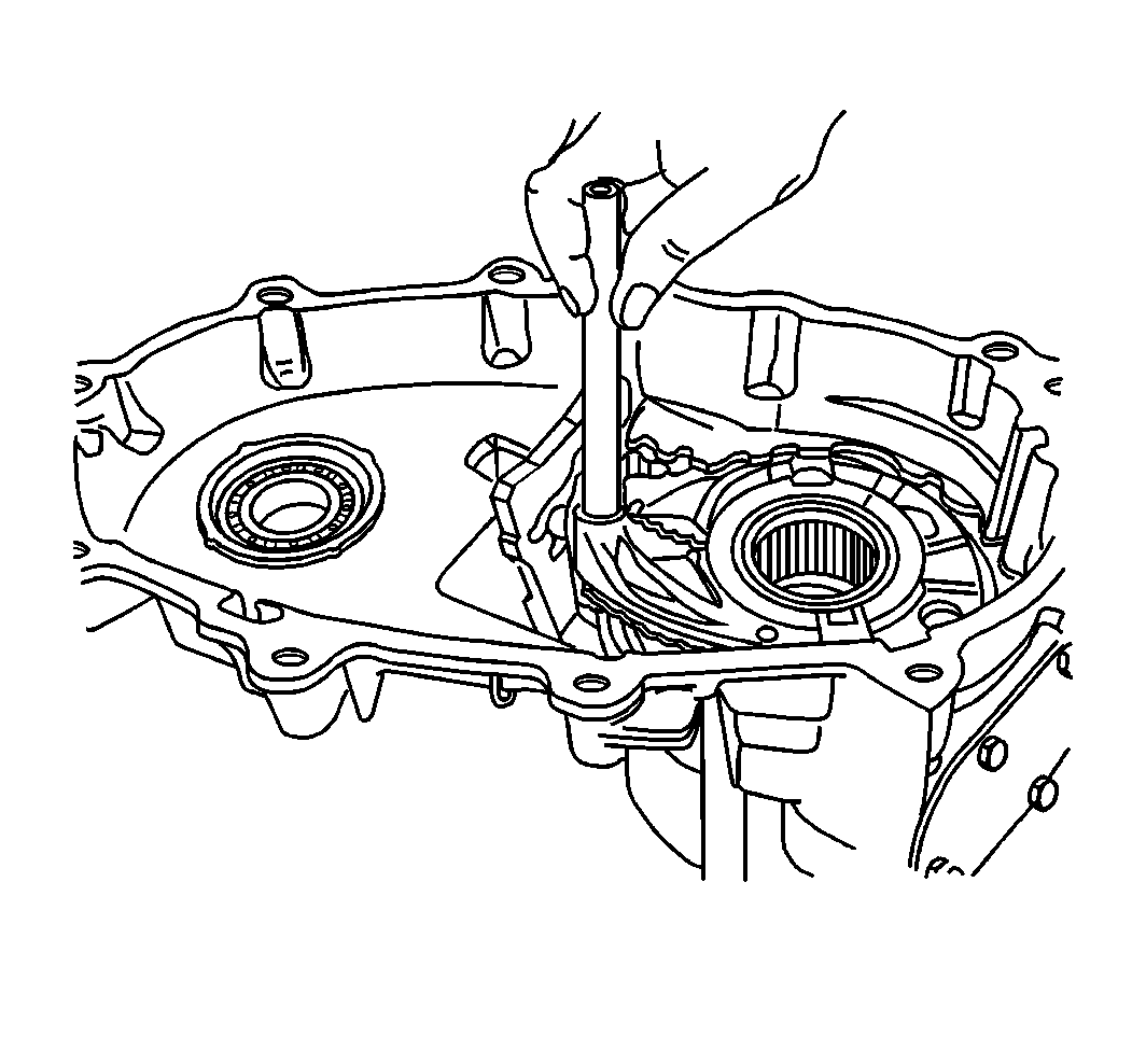
- Install the range fork
and the shift shaft hub.
Align the shift hub to the carrier assembly.
Align the shift fork pin to the slot in the selector.
- Install the shift rail through the range fork and into the boss
in the front case.
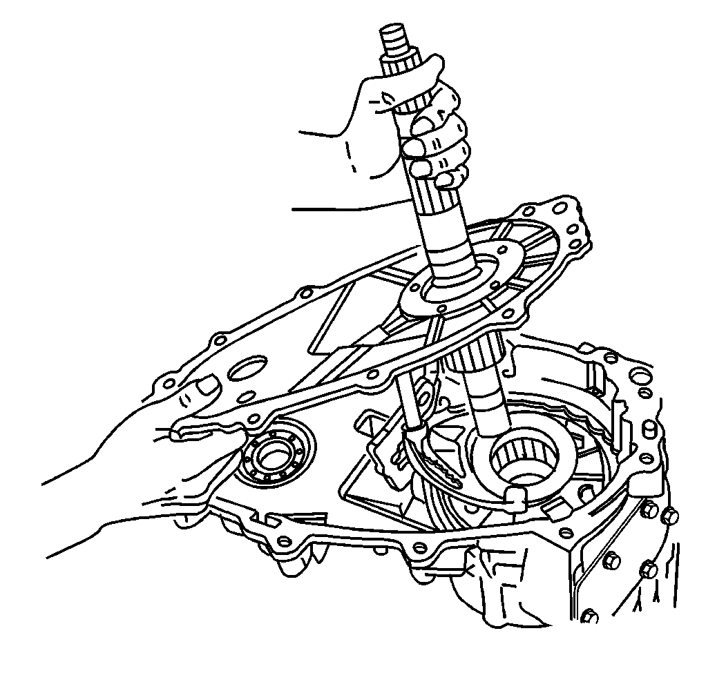
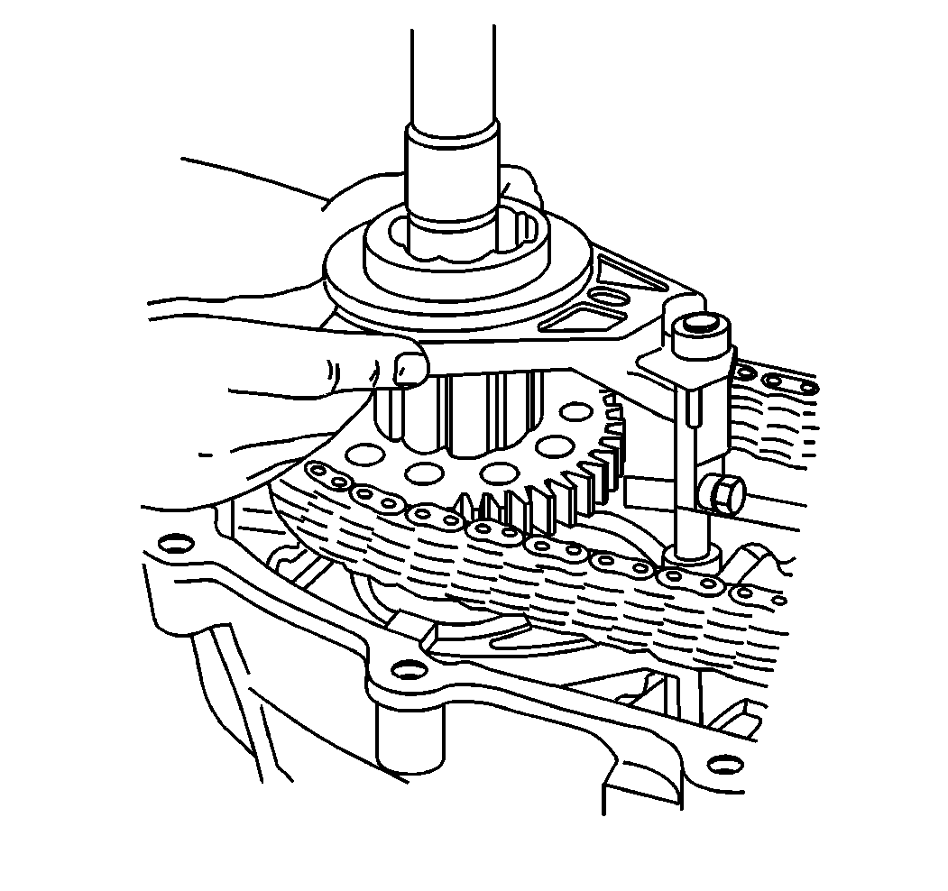
- Install the mainshaft
and the oil pump assembly into the carrier assembly.
The hub fits in one orientation with the mainshaft. Line up the wide
spline of the shaft to the wide slot in the hub.
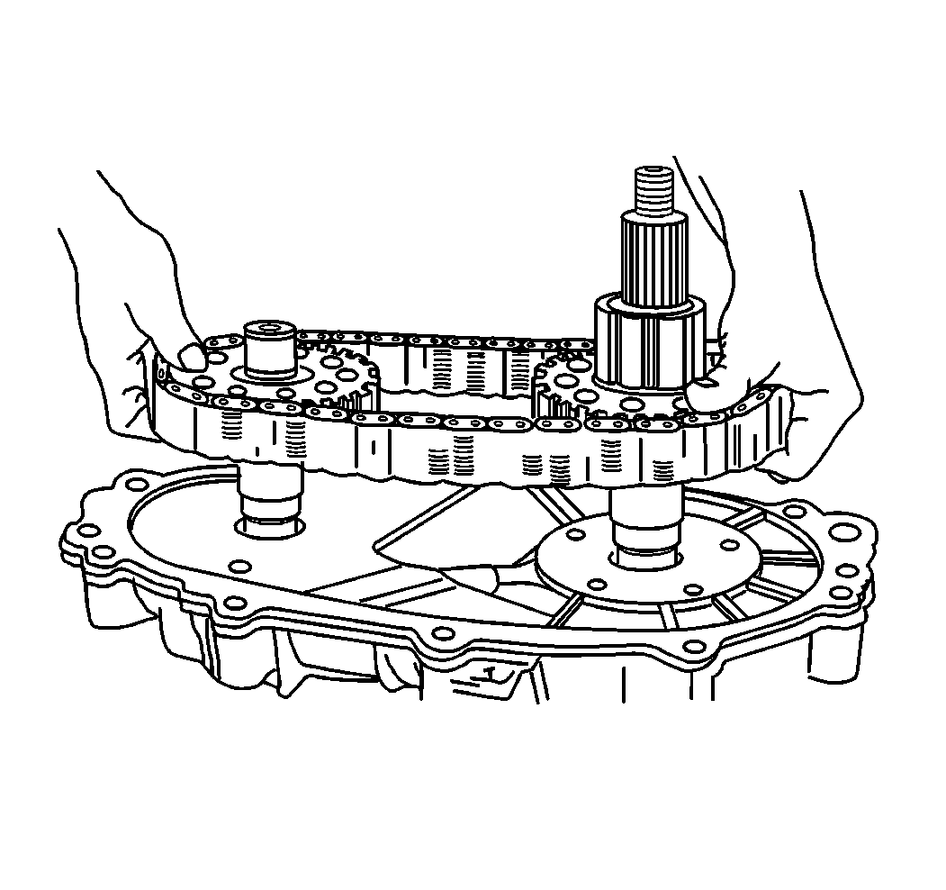
- Install the drive chain,
the driven gear, and the drive gear to the front output shaft bearing. Note
the orientation of the master link. Install in the same position it was disassembled.
- Install the front output
shaft ring and the washer to the one piece sprocket and the shaft.
- Assemble the synchronizer
assembly and the mode shift fork.
Align the synchronizer assembly to the mainshaft drive gear.
Align the mode fork to the shift rail.
- Install the synchronizer hub to the synchronizer hub assembly.
- Install the clutch coil
housing and the clutch coil housing snap ring to the mainshaft. The flat
side of the snap ring must face the rear of the assembly.
- Connect the shift rail spring to the shift rail.
- Install the clutch coil to the rear case.
- Install the clutch coil nuts to the clutch coil.
Tighten
Tighten the clutch coil nuts to 10 N·m (84 lb in).
- Install the clutch coil
wire through the rear case.
Connect the clutch coil wire connector to the clutch coil wire.
- Apply RTV sealer GM P/N 12345739 or equivalent to the following
areas:
| • | The pump body sealing surfaces |
Important: If equipped with bracket, the bracket bolt is to be installed at 12
o'clock.
- Install the case bolts to the case halves.
Tighten
Tighten the case bolts to 41 N·m (30 lb ft).
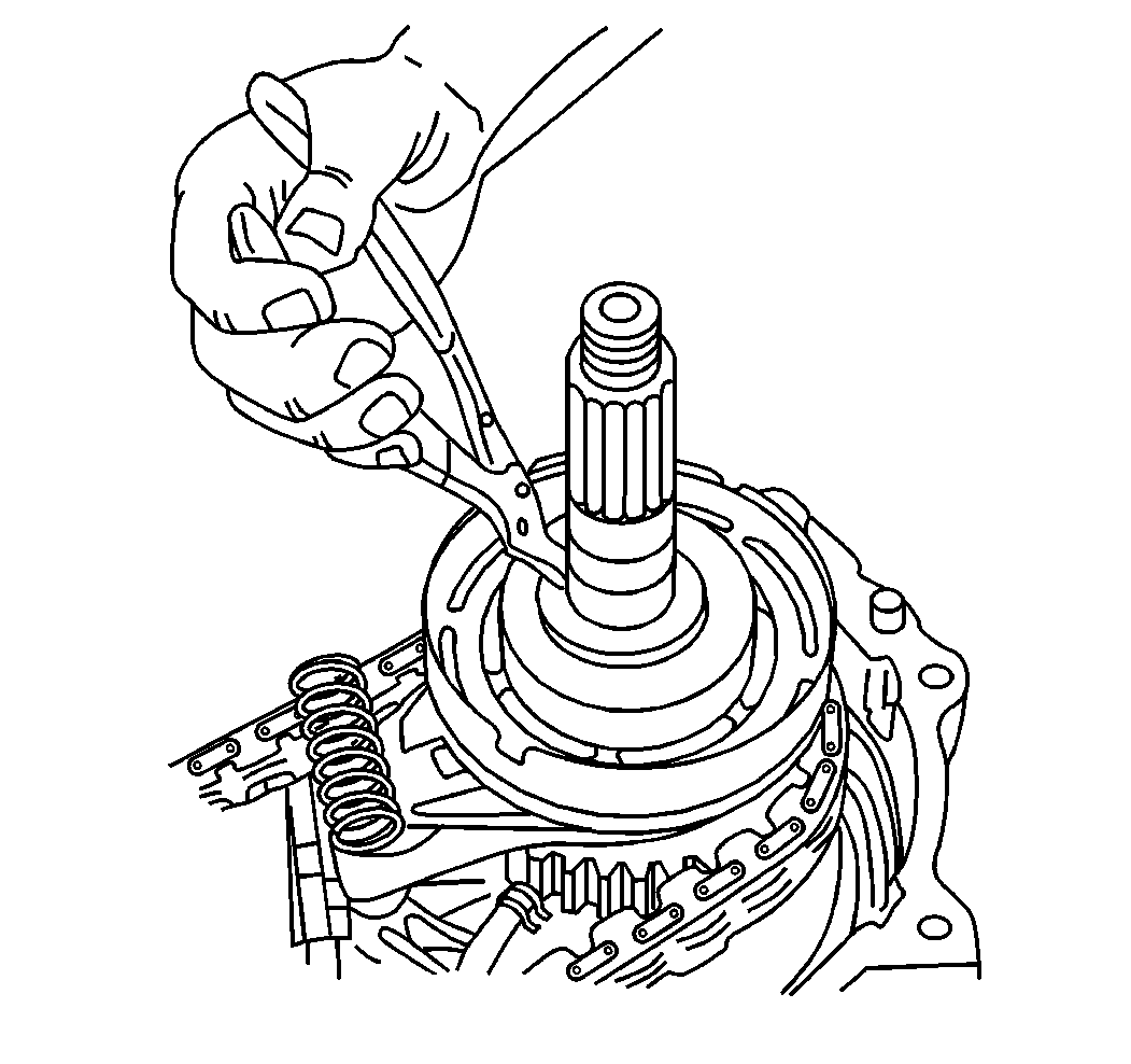
- Install the rear output
bearing snap ring to the mainshaft. The flat side of the snap ring must face
the rear of the assembly.
Important: The speedometer tone wheel is important to the proper operation of the
following components:
| • | The anti-lock braking system |
| • | The speedometer/odometer |
Do not damage the new speedometer tone wheel during installation.
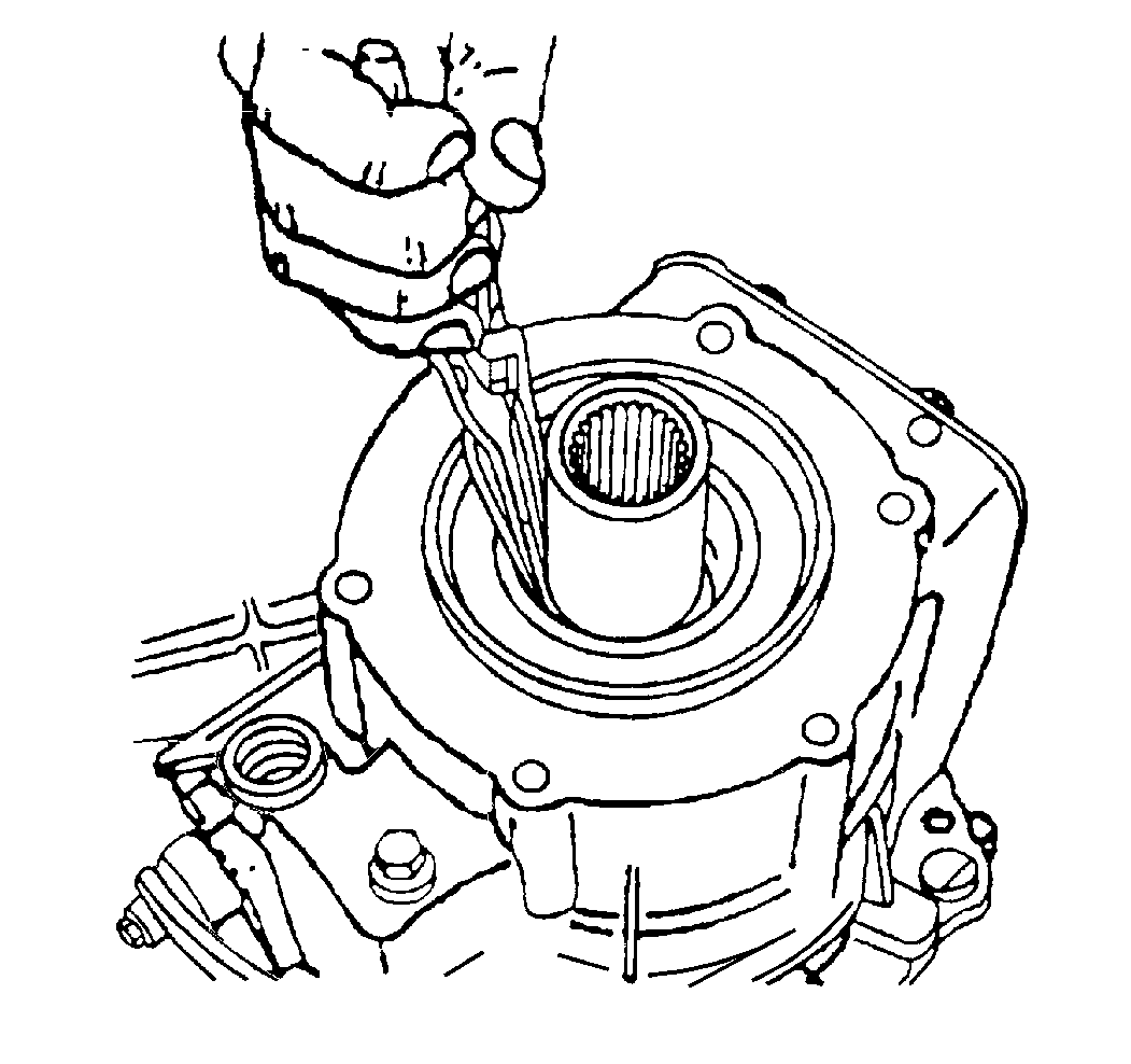
- Use the J 5590
in order
to install the new speedometer tone wheel to the mainshaft.
