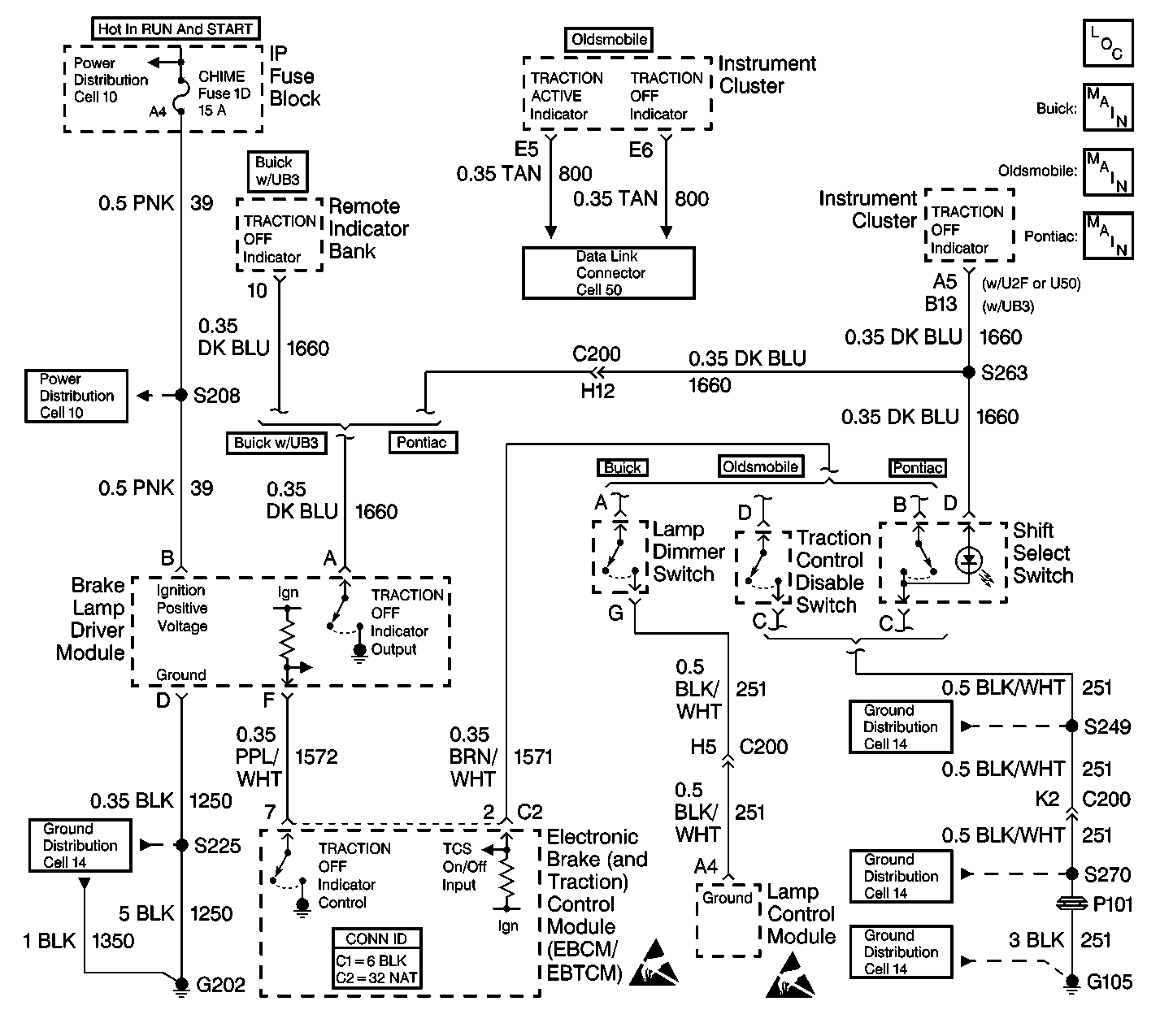
Circuit Description
If the vehicle is equipped with a U23, or a UH8 IPC, then the TRACTION OFF indicator is controlled by the serial data transmitted over the UART line from the EBTCM to the IPC.
If the vehicle is equipped with and IPC other then those stated above, then the TRACTION OFF indicator driver circuit runs from the IPC through the brake lamp driver module to the EBTCM. The indicator is supplied voltage from the IPC. The EBTCM controls the TRACTION OFF indicator through the brake lamp driver module. The brake lamp driver module acts as an invertor, when the EBTCM supplies a ground for the brake lamp driver module, the indicator remains off. When the EBTCM removes the ground for the brake lamp driver module, the indicator turns on by using the ground at the brake lamp driver module terminal D. When the Traction Control switch is pressed, the EBTCM sees the voltage on CKT 1571 go low, the EBTCM disables Traction Control and removes the ground for the TRACTION OFF indicator and the indicator turns on.
Diagnostic Aids
| • | Buick uses two clusters: the U23 and the UB3. The U23 TRACTION OFF indicator is controlled by messages over the UART serial data line. The UB3 cluster is hard wired through the brake lamp driver moduleto the EBTCM. The EBTCM controls the TRACTION OFF indicator. |
| • | Oldsmobile uses one cluster: the UH8. The UH8 TRACTION OFF indicator is controlled by the UART serial data line. |
| • | Pontiac uses three different clusters: the UB3, the U50, and the U2F. All of these clusters are hard wired through the brake lamp driver module to the EBTCM. The EBTCM controls the TRACTION OFF indicator. |
| • | If the battery feed to the IPC indicators is open, then more than one indicator bulb will be inoperative. |
Test Description
The numbers below refer to the step numbers on the diagnostic table.
-
This step checks if the IPC is controlled by serial data or hard wired through the LDM to the EBTCM.
-
This step checks if the IPC can turn the TRACTION OFF indicator on.
Step | Action | Value(s) | Yes | No | ||||||
|---|---|---|---|---|---|---|---|---|---|---|
1 | Was the Diagnostic System Check performed? | -- | Go to Diagnostic System Check | |||||||
2 | Is this vehicle equipped with a U23, or a UH8 Instrument cluster? | -- | ||||||||
3 |
Does the switch status change from pressed to released as the TCS switch is pressed and released? | -- | ||||||||
4 | Use the scan tool in ABS/TCS Special Tests in order to command the TRACTION OFF indicator on. Does the indicator come on? | -- | ||||||||
5 | Replace the EBTCM. Refer to Electronic Brake Control Module Replacement . Is the replacement complete? | -- | Go to Diagnostic System Check | -- | ||||||
6 | Suspect IPC. Refer to Diagnostic System Check - Instrument Cluster in Instrument Panel, Gauges and Console. Is the diagnosis complete? | -- | Go to Diagnostic System Check | -- | ||||||
7 |
Does the switch status change form pressed to released as the TCS switch is pressed and released? | -- | ||||||||
8 |
Does the TRACTION OFF indicator turn on? | -- | ||||||||
9 |
Is the fuse OK? | -- | ||||||||
10 |
Is the voltage within the specified range? | Battery Voltage | Go to Wiring Repairs in Wiring Systems | |||||||
11 |
Is the resistance equal to the specified value? | OL (infinite) | ||||||||
12 |
Is the voltage within the specified range? | Battery Voltage | ||||||||
13 | Check the voltage at terminal A of the brake lamp driver module harness connector. Is the voltage within the specified range? | Battery Voltage | ||||||||
14 | Repair CKT 39 for a short to ground. Refer to Wiring Repairs in Wiring Systems. Is the repair complete? | -- | Go to Diagnostic System Check | -- | ||||||
15 |
Is the fuse OK? | -- | Go to Diagnostic System Check | |||||||
16 |
Is the resistance less than the specified value? | 5 ohms | ||||||||
17 |
Is the resistance less than the specified value? | 5 ohms | ||||||||
18 |
Is the resistance equal to the specified value? | OL (infinite) | ||||||||
19 | Replace the brake lamp driver module. Refer to Lamp Driver Module Replacement . Is the replacement complete? | -- | Go to Diagnostic System Check | -- | ||||||
20 | Repair CKT 1572 for a short to ground. Refer to Wiring Repairs in Wiring Systems. Is the repair complete? | -- | Go to Diagnostic System Check | -- | ||||||
21 | Repair CKT 1250 for an open. Refer to Wiring Repairs in Wiring Systems. Is the repair complete? | -- | Go to Diagnostic System Check | -- | ||||||
22 | Repair an open or high resistance in CKT 1660. Refer to Wiring Repairs in Wiring Systems. Is the repair complete? | -- | Go to Diagnostic System Check | -- | ||||||
23 | Repair an open or high resistance in CKT 39. Refer to Wiring Repairs in Wiring Systems. Is the repair complete? | -- | Go to Diagnostic System Check | -- | ||||||
24 |
Is the resistance less than the specified value? | 5 ohms | ||||||||
25 |
Is the resistance less than the specified value? | 5 ohms | ||||||||
26 | Repair an open in CKT 1571. Refer to Wiring Repairs in Wiring Systems. Is the repair complete? | -- | Go to Diagnostic System Check | -- | ||||||
27 | Use the J 39200 DMM in order to measure the resistance between CKT 251 of the traction control ON/OFF switch harness connector and a good ground. Is the resistance less than the specified value? | -- | ||||||||
28 | Replace the traction control switch. Refer to the appropriate procedure:
Is the replacement complete? | -- | Go to Diagnostic System Check | -- | ||||||
29 | Repair an open in CKT 251. Refer to Wiring Repairs in Wiring Systems. Is the repair complete? | -- | Go to Diagnostic System Check | -- |
