GM Service Manual Online
For 1990-2009 cars only

AIR BAG Warning Lamp Does Not Come On Buick UB3
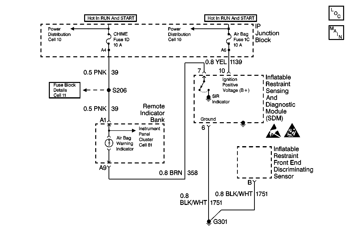

Object Number: 204848  Size: MF
SIR Schematics
SIR Components
SIR Caution
Handling ESD Sensitive Parts Notice

Circuit Description

When the ignition switch is first turned to RUN, the CHIME Fuse applies battery voltage to the AIR BAG warning lamp that is connected to SIR INDICATOR, terminal 7. The AIR BAG Fuse applies battery voltage to the IGNITION POSITIVE VOLTAGE input, terminal 10. The inflatable restraint Sensing and Diagnostic Module (SDM) responds by flashing the AIR BAG warning lamp seven times.

When measurements are requested in this table, use the J 39200 DMM with the correct terminal adapter from the J 35616 Connector Test Adapter Kit. When an inspection for proper connection is requested, refer to Testing for Electrical Intermittents in Wiring Systems. When a wire, connector or terminal repair is requested, use the J-38125 Terminal Repair Kit and refer to Wiring Repairs in Wiring Systems.

Test Description

The numbers below refer to the step numbers on the diagnostic table:

  1. This test determines whether the malfunction is in the inflatable restraint Sensing and Diagnostic Module (SDM) circuitry or in the remote indicator bank power feed circuitry.

  2. This test determines whether voltage is present in the warning lamp circuit.

  3. This test isolates CKT 358 and checks for a short in CKT 358 to B+.

  4. This test determines if the malfunction is in the remote indicator bank connector.

  5. This test determines if the open is due to a bad bulb.

  6. This test isolates an open in the warning lamp circuitry.

  7. This test checks whether power is available to the remote indicator bank power feed circuit.

  8. This test checks for a short from the remote indicator bank power feed circuit to ground.

  9. This test determines whether the short-to-ground is due to a short in the wiring or internal to the remote indicator bank.

  10. This test determines if the malfunction is in the remote indicator bank connector.

  11. This test determines whether the malfunction is due to an open power feed circuit from the CHIME Fuse.

Air Bag Warning Lamp Does Not Come On

Step

Action

Value(s)

Yes

No

1

Was the SIR Diagnostic System Check performed?

--

Go to Step 2

Go to SIR Diagnostic System Check

2

  1. Note the remote indicator bank while the ignition switch is turned to the RUN position.

Does the SERVICE ENGINE SOON indicator illuminate?

--

Go to Step 3

Go to Step 13

3

  1. Turn the ignition switch to the OFF position.
  2. Disconnect the inflatable restraint steering wheel and I/P module yellow 2-way connectors at the base of the steering column and above the RH sound insulator.
  3. Disconnect the inflatable restraint Sensing and Diagnostic Module (SDM).
  4. Install J 38715-96 SIR Shorting Bar Tool to the SDM harness connector.
  5. Install the CPA.
  6. Turn the ignition switch to the RUN position.
  7. Measure the voltage on the SDM harness connector from terminal 7 to ground.

Is the voltage more than the specified value?

10.0 V

Go to Step 4

Go to Step 6

4

  1. Turn the ignition switch to the OFF position.
  2. Disconnect the remote indicator bank. Refer to Remote Indicator Bank in Instrument Panel, Gauges, and Console.
  3. Turn the ignition switch to the RUN position.
  4. Measure the voltage on the SDM harness connector from terminal 7 to ground.

Is the voltage less than the specified value?

1.0 V

Go to Sensing and Diagnostic Module Integrity Check

Go to Step 5

5

  1. Turn the ignition switch to the OFF position.
  2. Repair a short-to-B+ condition in CKT 358.
  3. Reconnect the remote indicator bank.

Are the repairs complete?

--

Go to Step 24

--

6

  1. Turn the ignition switch to the OFF position.
  2. Remove the remote indicator bank. Refer to Remote Indicator Bank in Instrument Panel, Gauges, and Console.
  3. Check for proper connection to the remote indicator bank at terminal A9.

Is the connector damaged or corroded?

--

Go to Step 7

Go to Step 8

7

Repair the remote indicator bank harness connector. Refer to Connector Repairs in Electrical Diagnosis.

Are the repairs complete?

--

Go to Step 24

--

8

  1. Remove the AIR BAG warning lamp bulb.
  2. Inspect the bulb.

Is the bulb good?

--

Go to Step 10

Go to Step 9

9

  1. Replace the AIR BAG warning lamp bulb.
  2. Install the remote indicator bank.

Are the repairs complete?

--

Go to Step 24

--

10

  1. Install the AIR BAG warning lamp bulb.
  2. Measure the resistance from the remote indicator bank harness connector terminal A9 to the SDM harness connector terminal 7.

Is the resistance within the specified values?

0-5 ohms

Go to Step 12

Go to Step 11

11

  1. Repair an open condition in CKT 358.
  2. Install the remote indicator bank.

Are the repairs complete?

--

Go to Step 24

--

12

Service the remote indicator bank.

Are the repairs complete?

--

Go to Step 24

--

13

  1. Turn the ignition switch to the OFF position.
  2. Remove the CHIME Fuse.
  3. Inspect the fuse.

Is the fuse good?

--

Go to Step 19

Go to Step 14

14

  1. Replace the fuse.
  2. Turn the ignition switch to the RUN position for 10 seconds.
  3. Turn the ignition switch to the OFF position.
  4. Remove the CHIME Fuse.
  5. Inspect the fuse.

Is the fuse good?

--

Go to Step 18

Go to Step 15

15

  1. Disconnect the inflatable restraint steering wheel and I/P module yellow 2-way connectors at the base of the steering wheel and above the RH sound insulator.
  2. Disconnect the remote indicator bank. Refer to Remote Indicator Bank in Instrument Panel, Gauges, and Console.
  3. Replace the CHIME Fuse.
  4. Turn the ignition switch to the RUN position for 10 seconds.
  5. Turn the ignition switch to the OFF position.
  6. Remove the CHIME Fuse.
  7. Inspect the fuse.

Is the fuse good?

--

Go to Step 17

Go to Step 16

16

  1. Repair a short-to-ground condition in CKT 39.
  2. Replace the CHIME Fuse.

Are the repairs complete?

--

Go to Step 24

--

17

  1. Service the remote indicator bank.
  2. Install the CHIME Fuse.

Are the repairs complete?

--

Go to Step 24

--

18

Install the CHIME Fuse.

Are the repairs complete?

--

Go to Step 24

--

19

  1. Remove the remote indicator bank. Refer to Remote Indicator Bank in Instrument Panel, Gauges, and Console.
  2. Check for proper connection to the remote indicator bank at terminal A1.

Is the connector damaged or corroded?

--

Go to Step 20

Go to Step 21

20

Repair the remote indicator bank harness connector. Refer to Connector Repairs in Electrical Diagnosis.

Are the repairs complete?

--

Go to Step 24

--

21

Measure the resistance between the remote indicator bank harness connector terminal A1 to each terminal of the CHIME Fuse fuseholder.

Is either reading within the specified values?

0-5 ohms

Go to Step 23

Go to Step 22

22

  1. Repair an open condition in CKT 39.
  2. Install the CHIME Fuse.

Are the repairs complete?

--

Go to Step 24

--

23

  1. Repair an open condition in the power feed to the CHIME Fuse.
  2. Install the CHIME Fuse.

Are the repairs complete?

--

Go to Step 24

--

24

Reconnect all the SIR system components, make sure all the components are properly mounted.

Have all the SIR components been reconnected and properly mounted?

--

Go to SIR Diagnostic System Check

--

AIR BAG Warning Lamp Does Not Come On Oldsmobile
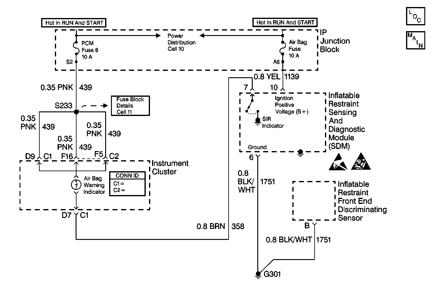

Object Number: 204855  Size: MF
SIR Schematics
SIR Caution
Handling ESD Sensitive Parts Notice

Circuit Description

When the ignition switch is first turned to RUN, the PCM Fuse applies battery voltage to the AIR BAG warning lamp that is connected to SIR INDICATOR, terminal 7. The AIR BAG Fuse applies battery voltage to the IGNITION POSITIVE VOLTAGE input, terminal 10. The inflatable restraint Sensing and Diagnostic Module (SDM) responds by flashing the AIR BAG warning lamp seven times.

When measurements are requested in this table, use the J 39200 DMM with the correct terminal adapter from the J 35616 Connector Test Adapter Kit. When an inspection for proper connection is requested, refer to Testing for Electrical Intermittents in Wiring Systems. When a wire, connector or terminal repair is requested, use the J-38125 Terminal Repair Kit and refer to Wiring Repairs in Wiring Systems.

Test Description

The numbers below refer to the step numbers on the diagnostic table:

  1. This test determines whether the malfunction is in the inflatable restraint Sensing and Diagnostic Module (SDM) circuitry or in the instrument cluster power feed circuitry.

  2. This test determines whether voltage is present in the warning lamp circuit.

  3. This test isolates CKT 358 and checks for a short in CKT 358 to B+.

  4. This test determines if the malfunction is in the instrument cluster connector.

  5. This test determines if the open is due to a bad bulb.

  6. This test isolates an open in the warning lamp circuitry.

  7. This test checks whether power is available to the instrument cluster power feed circuit.

  8. This test checks for a short from the instrument cluster power feed circuit to ground.

  9. This test determines whether the short to ground is due to a short in the wiring or internal to the instrument cluster.

  10. This test determines if the malfunction is in the instrument cluster connector.

  11. This test determines whether the malfunction is due to an open power feed circuit from the PCM Fuse.

Air Bag Warning Lamp Does Not Come On

Step

Action

Value(s)

Yes

No

1

Was the SIR Diagnostic System Check performed?

--

Go to Step 2

Go to SIR Diagnostic System Check

2

  1. Note the instrument cluster while the ignition switch is turned to the RUN position.

Does the SERVICE ENGINE SOON indicator illuminate?

--

Go to Step 3

Go to Step 13

3

  1. Turn the ignition switch to the OFF position.
  2. Disconnect the inflatable restraint steering wheel and I/P module yellow 2-way connectors at the base of the steering column and above the RH sound insulator.
  3. Disconnect the inflatable restraint Sensing and Diagnostic Module (SDM).
  4. Install J 38715-96 SIR Shorting Bar Tool to the SDM harness connector.
  5. Install the CPA.
  6. Turn the ignition switch to the RUN position.
  7. Measure the voltage on the SDM harness connector from terminal 7 to ground.

Is the voltage more than the specified value?

10.0 V

Go to Step 4

Go to Step 6

4

  1. Turn the ignition switch to the OFF position.
  2. Disconnect the instrument cluster. Refer to instrument cluster in Instrument Panel, Gauges, and Console.
  3. Turn the ignition switch to the RUN position.
  4. Measure the voltage on the SDM harness connector from terminal 7 to ground.

Is the voltage less than the specified value?

1.0 V

Go to Sensing and Diagnostic Module Integrity Check

Go to Step 5

5

  1. Turn the ignition switch to the OFF position.
  2. Repair a short to B+ condition in CKT 358.
  3. Reconnect the instrument cluster.

Are the repairs complete?

--

Go to Step 24

--

6

  1. Turn the ignition switch to the OFF position.
  2. Remove the instrument cluster. Refer to Instrument Cluster in Instrument Panel, Gauges, and Console.
  3. Check for proper connection of the instrument cluster at connector C1, terminal D9 and connector C2, terminal F16 and F5.

Is either connector damaged or corroded?

--

Go to Step 7

Go to Step 8

7

Repair the instrument cluster harness connector. Refer to Connector Repairs in Electrical Diagnosis.

Are the repairs complete?

--

Go to Step 24

--

8

  1. Remove the AIR BAG warning lamp bulb.
  2. Inspect the bulb.

Is the bulb good?

--

Go to Step 10

Go to Step 9

9

  1. Replace the AIR BAG warning lamp bulb.
  2. Install the instrument cluster.

Are the repairs complete?

--

Go to Step 24

--

10

  1. Install the AIR BAG warning lamp bulb.
  2. Measure the resistance from the instrument cluster harness connector C1, terminal D7 to the SDM harness connector terminal 7.

Is the resistance within the specified values?

0-5 ohms

Go to Step 12

Go to Step 11

11

  1. Repair an open condition in CKT 358.
  2. Install the instrument cluster.

Are the repairs complete?

--

Go to Step 24

--

12

Service the instrument cluster.

Are the repairs complete?

--

Go to Step 24

--

13

  1. Turn the ignition switch to the OFF position.
  2. Remove the PCM Fuse.
  3. Inspect the fuse.

Is the fuse good?

--

Go to Step 19

Go to Step 14

14

  1. Replace the fuse.
  2. Turn the ignition switch to the RUN position for 10 seconds.
  3. Turn the ignition switch to the OFF position.
  4. Remove the PCM Fuse.
  5. Inspect the fuse.

Is the fuse good?

--

Go to Step 18

Go to Step 15

15

  1. Disconnect the inflatable restraint steering wheel and I/P module yellow 2-way connectors at the base of the steering wheel and above the RH sound insulator.
  2. Disconnect the instrument cluster. Refer to instrument cluster in Instrument Panel, Gauges, and Console.
  3. Replace the PCM Fuse.
  4. Turn the ignition switch to the RUN position for 10 seconds.
  5. Turn the ignition switch to the OFF position.
  6. Remove the PCM Fuse.
  7. Inspect the fuse.

Is the fuse good?

--

Go to Step 17

Go to Step 16

16

  1. Repair a short to ground condition in CKT 439.
  2. Replace the PCM Fuse.

Are the repairs complete?

--

Go to Step 24

--

17

  1. Service the instrument cluster.
  2. Install the PCM Fuse.

Are the repairs complete?

--

Go to Step 24

--

18

Install the PCM Fuse.

Are the repairs complete?

--

Go to Step 24

--

19

  1. Remove the instrument cluster. Refer to instrument cluster in Instrument Panel, Gauges, and Console.
  2. Check for proper connection to the instrument cluster at connector C1, terminal D9 and connector C2, terminal F16 and terminal F5.

Is either connector damaged or corroded?

--

Go to Step 20

Go to Step 21

20

Repair the instrument cluster harness connector. Refer to Connector Repairs in Electrical Diagnosis.

Are the repairs complete?

--

Go to Step 24

--

21

Measure the resistance between the instrument cluster harness connector C1, terminal D9 and connector C2, terminal F16 and terminal F5 to each terminal of the PCM Fuse fuseholder.

Is either reading within the specified values?

0-5 ohms

Go to Step 23

Go to Step 22

22

  1. Repair an open condition in CKT 439.
  2. Install the PCM Fuse.

Are the repairs complete?

--

Go to Step 24

--

23

  1. Repair an open condition in the power feed to the PCM Fuse.
  2. Install the PCM Fuse.

Are the repairs complete?

--

Go to Step 24

--

24

Reconnect all the SIR system components, make sure all the components are properly mounted.

Have all the SIR components been reconnected and properly mounted?

--

Go to SIR Diagnostic System Check

--

AIR BAG Warning Lamp Does Not Come On Buick U23
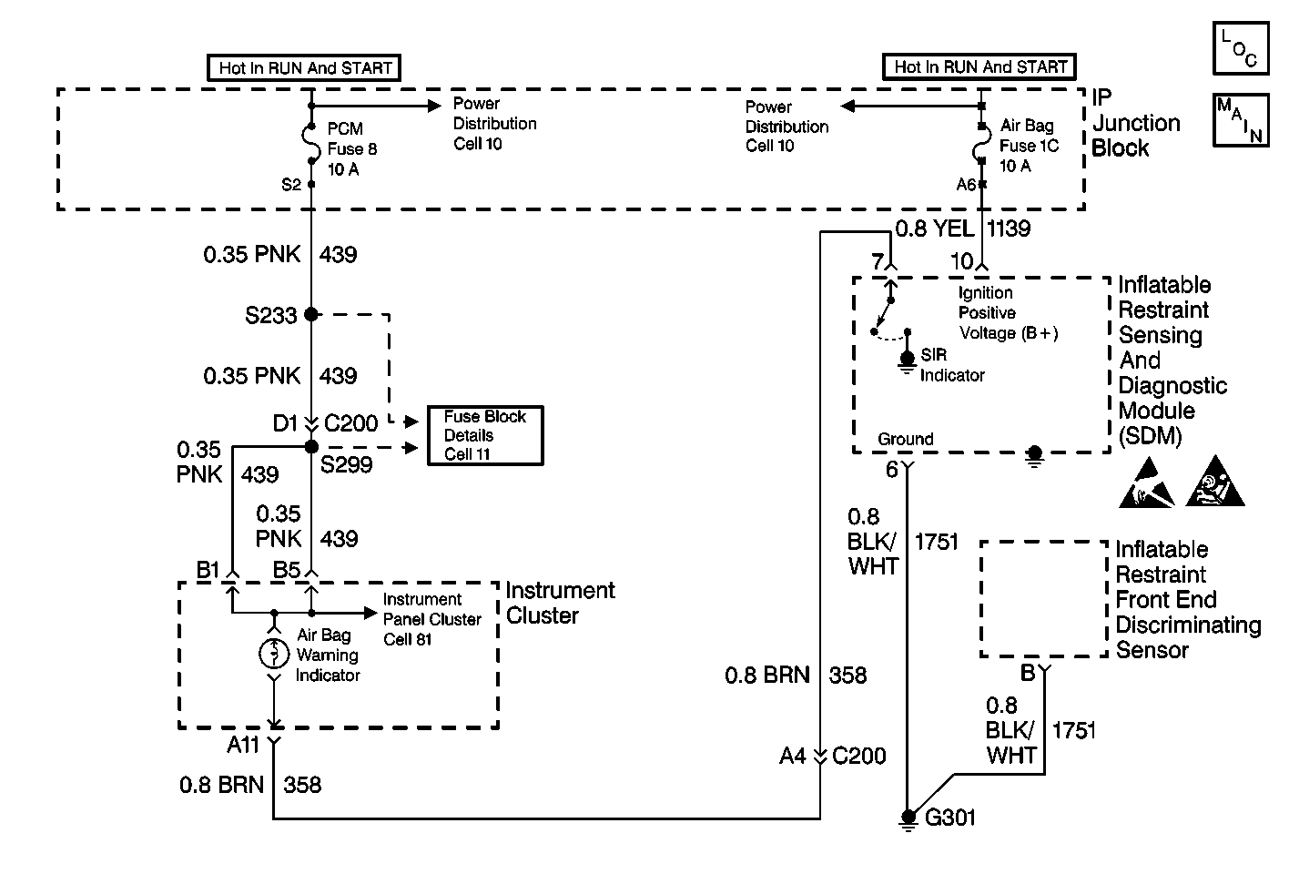

Object Number: 204852  Size: MF
SIR Schematics
SIR Caution
SIR Components
Handling ESD Sensitive Parts Notice

Circuit Description

When the ignition switch is first turned to RUN, the PCM Fuse applies battery voltage to the AIR BAG warning lamp that is connected to SIR INDICATOR, terminal 7. The AIR BAG Fuse applies battery voltage to the IGNITION POSITIVE VOLTAGE input, terminal 10. The inflatable restraint Sensing and Diagnostic Module (SDM) responds by flashing the AIR BAG warning lamp seven times.

When measurements are requested in this table, use the J 39200 DMM with the correct terminal adapter from the J 35616 Connector Test Adapter Kit. When an inspection for proper connection is requested, refer to Testing for Electrical Intermittents in Wiring Systems. When a wire, connector or terminal repair is requested, use the J-38125 Terminal Repair Kit and refer to Wiring Repairs in Wiring Systems.

Test Description

The numbers below refer to the step numbers on the diagnostic table:

  1. This test determines whether the malfunction is in the inflatable restraint Sensing and Diagnostic Module (SDM) circuitry or in the instrument cluster power feed circuitry.

  2. This test determines whether voltage is present in the warning lamp circuit.

  3. This test isolates CKT 358 and checks for a short in CKT 358 to B+.

  4. This test isolates the short-to-voltage to one side of connector C200.

  5. This test determines if the malfunction is in connector C200.

  6. This test checks for an open in CKT 358 between connector C200 and the SDM.

  7. This test determines if the malfunction is in the instrument cluster connector.

  8. This test determines if the open is due to a bad bulb.

  9. This test isolates an open in the warning lamp circuitry.

  10. This test checks whether power is available to the instrument cluster power feed circuit.

  11. This test checks for a short from the instrument cluster power feed circuit to ground.

  12. This test isolates the short-to-ground to one side of connector C200.

  13. This test determines whether the short-to-ground is due to a short in the wiring or internal to the instrument cluster.

  14. This test determines if the malfunction is in the instrument cluster connector.

  15. This test determines whether the malfunction is due to an open power feed circuit from the PCM Fuse.

  16. This test determines if the malfunction is in connector C200.

  17. This test isolates an open power feed circuit from the PCM Fuse.

Air Bag Warning Lamp Does Not Come On

Step

Action

Value(s)

Yes

No

1

Was the SIR Diagnostic System Check performed?

--

Go to Step 2

Go to SIR Diagnostic System Check

2

Note the instrument cluster while the ignition switch is turned to the RUN position.

Does the SERVICE ENGINE SOON indicator illuminate?

--

Go to Step 3

Go to Step 19

3

  1. Turn the ignition switch to the OFF position.
  2. Disconnect the inflatable restraint steering wheel and I/P module yellow 2-way connectors at the base of the steering column and above the RH sound insulator.
  3. Disconnect the inflatable restraint Sensing and Diagnostic Module (SDM).
  4. Install J 38715-96 SIR Shorting Bar Tool to the SDM harness connector.
  5. Install the CPA.
  6. Turn the ignition switch to the RUN position.
  7. Measure the voltage on the SDM harness connector from terminal 7 to ground.

Is the voltage more than the specified value?

10.0 V

Go to Step 4

Go to Step 8

4

  1. Turn the ignition switch to the OFF position.
  2. Disconnect the instrument cluster. Refer to Instrument Cluster in Instrument Panel, Gauges, and Console.
  3. Turn the ignition switch to the RUN position.
  4. Measure the voltage on the SDM harness connector from terminal 7 to ground.

Is the voltage less than the specified value?

1.0 V

Go to Sensing and Diagnostic Module Integrity Check

Go to Step 5

5

  1. Turn the ignition switch to the OFF position.
  2. Disconnect connector C200. Refer to Electrical Diagnosis.
  3. Turn the ignition switch to the RUN position.
  4. Measure the voltage on the instrument cluster harness connector from terminal A11 to ground.

Is the voltage less than the specified value?

1.0 V

Go to Step 7

Go to Step 6

6

  1. Turn the ignition switch to the OFF position.
  2. Repair a short-to-B+ condition in CKT 358 between connector C200 and the SDM.
  3. Reconnect connector C200.
  4. Reconnect the instrument cluster.

Are the repairs complete?

--

Go to Step 36

--

7

  1. Turn the ignition switch to the OFF position.
  2. Repair a short-to-B+ condition in CKT 358 between the instrument cluster and connector C200.
  3. Reconnect connector C200.
  4. Reconnect the instrument cluster.

Are the repairs complete?

--

Go to Step 36

--

8

  1. Turn the ignition switch to the OFF position.
  2. Disconnect connector C200. Refer to Electrical Diagnosis.
  3. Check for proper connection to the connector C200 at terminal A4.

Is the connector damaged or corroded?

--

Go to Step 9

Go to Step 10

9

  1. Repair connector C200.
  2. Reconnect connector C200.

Are the repairs complete?

--

Go to Step 36

--

10

Measure the resistance from connector C200 terminal A4 to the SDM harness connector terminal 7.

Is the resistance within the specified values?

0-5 ohms

Go to Step 12

Go to Step 11

11

  1. Repair an open condition in CKT 358 between the SDM and connector C200.
  2. Connect connector C200.

Are the repairs complete?

--

Go to Step 36

--

12

  1. Turn the ignition switch to the OFF position.
  2. Remove the instrument cluster. Refer to Instrument Cluster in Instrument Panel, Gauges, and Console.
  3. Check for proper connection to the instrument cluster at terminal A11.

Is the connector damaged or corroded?

--

Go to Step 13

Go to Step 14

13

Repair the instrument cluster harness connector. Refer to Connector Repairs in Electrical Diagnosis.

Are the repairs complete?

--

Go to Step 36

--

14

  1. Remove the AIR BAG warning lamp bulb.
  2. Inspect the bulb.

Is the bulb good?

--

Go to Step 16

Go to Step 15

15

  1. Replace the AIR BAG warning lamp bulb.
  2. Install the instrument cluster.

Are the repairs complete?

--

Go to Step 36

--

16

  1. Install the AIR BAG warning lamp bulb.
  2. Measure the resistance from the instrument cluster harness connector terminal A11 to the connector C200 terminal A4.

Is the resistance within the specified values?

0-5 ohms

Go to Step 18

Go to Step 17

17

  1. Repair an open condition in CKT 358 between the instrument cluster and connector C200.
  2. Install the instrument cluster.
  3. Reconnect connector C200.

Are the repairs complete?

--

Go to Step 36

--

18

Service the instrument cluster.

Are the repairs complete?

--

Go to Step 36

--

19

  1. Turn the ignition switch to the OFF position.
  2. Remove the PCM Fuse.
  3. Inspect the fuse.

Is the fuse good?

--

Go to Step 27

Go to Step 20

20

  1. Replace the fuse.
  2. Turn the ignition switch to the RUN position for 10 seconds.
  3. Turn the ignition switch to the OFF position.
  4. Remove the PCM Fuse.
  5. Inspect the fuse.

Is the fuse good?

--

Go to Step 26

Go to Step 21

21

  1. Disconnect the inflatable restraint steering wheel and I/P module yellow 2-way connectors at the base of the steering wheel and above the RH sound insulator.
  2. Disconnect the instrument cluster. Refer to Instrument Cluster in Instrument Panel, Gauges, and Console.
  3. Disconnect connector C200.
  4. Replace the PCM Fuse.
  5. Turn the ignition switch to the RUN position for 10 seconds.
  6. Turn the ignition switch to the OFF position.
  7. Remove the PCM Fuse.
  8. Inspect the fuse.

Is the fuse good?

--

Go to Step 23

Go to Step 22

22

  1. Repair a short-to-ground condition in CKT 439 before connector C200. Refer to Fuse Block Details-Cell 11.
  2. Replace the PCM Fuse.

Are the repairs complete?

--

Go to Step 36

--

23

  1. Disconnect the instrument cluster. Refer to Instrument Cluster in Instrument Panel, Gauges, and Console.
  2. Connect connector C200.
  3. Replace the PCM Fuse.
  4. Turn the ignition switch to the RUN position for 10 seconds.
  5. Turn the ignition switch to the OFF position.
  6. Remove the PCM Fuse.
  7. Inspect the fuse.

Is the fuse good?

--

Go to Step 25

Go to Step 24

24

  1. Repair a short-to-ground condition in CKT 439 between C200 and the instrument cluster. Refer to Fuse Block Details-Cell 11.
  2. Replace the PCM Fuse.

Are the repairs complete?

--

Go to Step 36

--

25

  1. Service the instrument cluster.
  2. Install the PCM Fuse.

Are the repairs complete?

--

Go to Step 36

--

26

Install the PCM Fuse.

Are the repairs complete?

--

Go to Step 36

--

27

  1. Remove the instrument cluster. Refer to Instrument Cluster in Instrument Panel, Gauges, and Console.
  2. Check for proper connection to the instrument cluster at terminals B1 and B5.

Is the connector damaged or corroded?

--

Go to Step 28

Go to Step 29

28

Repair the instrument cluster harness connector. Refer to Connector Repairs in Wiring Repairs.

Are the repairs complete?

--

Go to Step 36

--

29

Measure the resistance between the instrument cluster harness connector terminal B1 to each terminal of the PCM Fuse fuseholder.

Is either reading within the specified values?

0-5 ohms

Go to Step 35

Go to Step 30

30

  1. Disconnect connector C200.
  2. Check for proper connection to the connector C200 at terminal A4.

Is the connector damaged or corroded?

--

Go to Step 31

Go to Step 32

31

  1. Repair connector C200.
  2. Reconnect connector C200.
  3. Install the PCM Fuse.

Are the repairs complete?

Go to Step 36

32

Measure the resistance from connector C200 terminal D1 to the instrument cluster harness connector terminal B1.

Is the resistance within the specified values?

0-5 ohms

Go to Step 34

Go to Step 33

33

  1. Repair an open condition in CKT 439 between the splice S299 and the connector C200.
  2. Connect connector C200.
  3. Install the PCM Fuse.

Are the repairs complete?

--

Go to Step 36

--

34

  1. Repair an open condition in CKT 439 between the splice S233 and the PCM Fuse fuseholder.
  2. Connect connector C200.
  3. Install the PCM Fuse.

Are the repairs complete?

--

Go to Step 36

--

35

  1. Repair an open condition in the power feed to the PCM Fuse.
  2. Install the PCM Fuse.

Are the repairs complete?

--

Go to Step 36

--

36

Reconnect all the SIR system components, make sure all the components are properly mounted.

Have all the SIR components been reconnected and properly mounted?

--

Go to SIR Diagnostic System Check

--

AIR BAG Warning Lamp Does Not Come On Pontiac
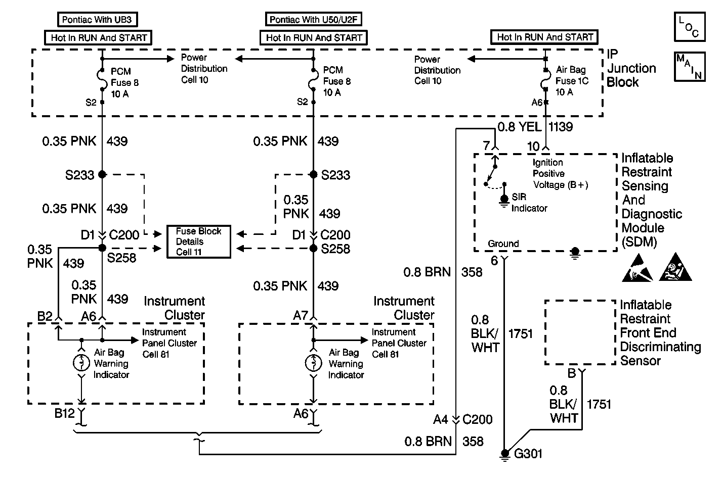

Object Number: 204859  Size: MF
SIR Schematics
SIR Caution
Handling ESD Sensitive Parts Notice

Circuit Description

When the ignition switch is first turned to RUN, the PCM Fuse applies battery voltage to the AIR BAG warning lamp that is connected to SIR INDICATOR, terminal 7. The AIR BAG Fuse applies battery voltage to the IGNITION POSITIVE VOLTAGE input, terminal 10. The inflatable restraint Sensing and Diagnostic Module (SDM) responds by flashing the AIR BAG warning lamp seven times.

When measurements are requested in this table, use the J 39200 DMM with the correct terminal adapter from the J 35616 Connector Test Adapter Kit. When an inspection for proper connection is requested, refer to Testing for Electrical Intermittents in Wiring Systems. When a wire, connector or terminal repair is requested, use the J-38125 Terminal Repair Kit and refer to Wiring Repairs in Wiring Systems.

Test Description

The numbers below refer to the step numbers on the diagnostic table:

  1. This test determines whether the malfunction is in the inflatable restraint Sensing and Diagnostic Module (SDM) circuitry or in the instrument cluster power feed circuitry.

  2. This test determines whether voltage is present in the warning lamp circuit.

  3. This test isolates CKT 358 and checks for a short in CKT 358 to B+.

  4. This test isolates the short-to-voltage to one side of connector C200.

  5. This test determines if the malfunction is in connector C200.

  6. This test checks for an open in CKT 358 between connector C200 and the SDM.

  7. This test determines if the malfunction is in the instrument cluster connector.

  8. This test determines if the open is due to a bad bulb.

  9. This test isolates an open in the warning lamp circuitry.

  10. This test checks whether power is available to the instrument cluster power feed circuit.

  11. This test checks for a short from the instrument cluster power feed circuit to ground.

  12. This test isolates the short-to-ground to one side of connector C200.

  13. This test determines whether the short-to-ground is due to a short in the wiring or internal to the instrument cluster.

  14. This test determines if the malfunction is in the instrument cluster connector.

  15. This test determines whether the malfunction is due to an open power feed circuit from the PCM Fuse.

  16. This test determines if the malfunction is in connector C200.

  17. This test isolates an open power feed circuit from the PCM Fuse.

Air Bag Warning Lamp Does Not Come On

Step

Action

Value(s)

Yes

No

1

Was the SIR Diagnostic System Check performed?

--

Go to Step 2

Go to SIR Diagnostic System Check

2

Note the instrument cluster while the ignition switch is turned to the RUN position.

Does the SERVICE ENGINE SOON indicator illuminate?

--

Go to Step 3

Go to Step 19

3

  1. Turn the ignition switch to the OFF position.
  2. Disconnect the inflatable restraint steering wheel and I/P module yellow 2-way connectors at the base of the steering column and above the RH sound insulator.
  3. Disconnect the inflatable restraint Sensing and Diagnostic Module (SDM).
  4. Install J 38715-96 SIR Shorting Bar Tool to the SDM harness connector.
  5. Install the CPA.
  6. Turn the ignition switch to the RUN position.
  7. Measure the voltage on the SDM harness connector from terminal 7 to ground.

Is the voltage more than the specified value?

10.0 V

Go to Step 4

Go to Step 8

4

  1. Turn the ignition switch to the OFF position.
  2. Disconnect the instrument cluster. Refer to Instrument Cluster Replacement in Instrument Panel, Gauges, and Console.
  3. Turn the ignition switch to the RUN position.
  4. Measure the voltage on the SDM harness connector from terminal 7 to ground.

Is the voltage less than the specified value?

1.0 V

Go to Sensing and Diagnostic Module Integrity Check

Go to Step 5

5

  1. Turn the ignition switch to the OFF position.
  2. Disconnect connector C200. Refer to Electrical Diagnosis.
  3. Turn the ignition switch to the RUN position.
  4. Measure the voltage on the instrument cluster harness connector from terminal B12 (UB3) or A6 (U2F/U50) to ground.

Is the voltage less than the specified value?

1.0 V

Go to Step 7

Go to Step 6

6

  1. Turn the ignition switch to the OFF position.
  2. Repair a short-to-B+ condition in CKT 358 between connector C200 and the SDM.
  3. Reconnect connector C200.
  4. Reconnect the instrument cluster.

Are the repairs complete?

--

Go to Step 36

--

7

  1. Turn the ignition switch to the OFF position.
  2. Repair a short to B+ condition in CKT 358 between the instrument cluster and connector C200.
  3. Reconnect connector C200.
  4. Reconnect the instrument cluster.

Are the repairs complete?

--

Go to Step 36

--

8

  1. Turn the ignition switch to the OFF position.
  2. Disconnect connector C200. Refer to Electrical Diagnosis.
  3. Check for proper connection to the connector C200 at terminal A4.

Is the connector damaged or corroded?

--

Go to Step 9

Go to Step 10

9

  1. Repair connector C200.
  2. Reconnect connector C200.

Are the repairs complete?

--

Go to Step 36

--

10

Measure the resistance from connector C200 terminal A4 to the SDM harness connector terminal 7.

Is the resistance within the specified values?

0-5 ohms

Go to Step 12

Go to Step 11

11

  1. Repair an open condition in CKT 358 between the SDM and connector C200.
  2. Connect connector C200.

Are the repairs complete?

--

Go to Step 36

--

12

  1. Turn the ignition switch to the OFF position.
  2. Remove the instrument cluster. Refer to Instrument Cluster Replacement in Instrument Panel, Gauges, and Console.
  3. Check for proper connection to the instrument cluster at terminal B12 (UB3) or A6 (U2F/U50).

Is the connector damaged or corroded?

--

Go to Step 13

Go to Step 14

13

Repair the instrument cluster harness connector. Refer to Connector Repairs in Electrical Diagnosis.

Are the repairs complete?

--

Go to Step 36

--

14

  1. Remove the AIR BAG warning lamp bulb.
  2. Inspect the bulb.

Is the bulb good?

--

Go to Step 16

Go to Step 15

15

  1. Replace the AIR BAG warning lamp bulb.
  2. Install the instrument cluster.

Are the repairs complete?

--

Go to Step 36

--

16

  1. Install the AIR BAG warning lamp bulb.
  2. Measure the resistance from the instrument cluster harness connector terminal B12 (UB3) or A6 (U2F/U50) to connector C200 terminal A4.

Is the resistance within the specified values?

0-5 ohms

Go to Step 18

Go to Step 17

17

  1. Repair an open condition in CKT 358 between the instrument cluster and connector C200.
  2. Install the instrument cluster.
  3. Reconnect connector C200.

Are the repairs complete?

--

Go to Step 36

--

18

Service the instrument cluster.

Are the repairs complete?

--

Go to Step 36

--

19

  1. Turn the ignition switch to the OFF position.
  2. Remove the PCM Fuse.
  3. Inspect the fuse.

Is the fuse good?

--

Go to Step 27

Go to Step 20

20

  1. Replace the fuse.
  2. Turn the ignition switch to the RUN position for 10 seconds.
  3. Turn the ignition switch to the OFF position.
  4. Remove the PCM Fuse.
  5. Inspect the fuse.

Is the fuse good?

--

Go to Step 26

Go to Step 21

21

  1. Disconnect the inflatable restraint steering wheel and I/P module yellow 2-way connectors at the base of the steering wheel and above the RH sound insulator.
  2. Disconnect the instrument cluster. Refer to Instrument Cluster Replacement in Instrument Panel, Gauges, and Console.
  3. Disconnect connector C200.
  4. Replace the PCM Fuse.
  5. Turn the ignition switch to the RUN position for 10 seconds.
  6. Turn the ignition switch to the OFF position.
  7. Remove the PCM Fuse.
  8. Inspect the fuse.

Is the fuse good?

--

Go to Step 23

Go to Step 22

22

  1. Repair a short-to-ground condition in CKT 439 before connector C200. Refer to Fuse Block Details-Cell 11.
  2. Replace the PCM Fuse.

Are the repairs complete?

--

Go to Step 36

--

23

  1. Disconnect the instrument cluster. Refer to Instrument Cluster Replacement in Instrument Panel, Gauges, and Console.
  2. Connect connector C200.
  3. Replace the PCM Fuse.
  4. Turn the ignition switch to the RUN position for 10 seconds.
  5. Turn the ignition switch to the OFF position.
  6. Remove the PCM Fuse.
  7. Inspect the fuse.

Is the fuse good?

--

Go to Step 25

Go to Step 24

24

  1. Repair a short-to-ground condition in CKT 439 between C200 and the instrument cluster. Refer to Fuse Block Details-Cell 11.
  2. Replace the PCM Fuse.

Are the repairs complete?

--

Go to Step 36

--

25

  1. Service the instrument cluster.
  2. Install the PCM Fuse.

Are the repairs complete?

--

Go to Step 36

--

26

Install the PCM Fuse.

Are the repairs complete?

--

Go to Step 36

--

27

  1. Remove the instrument cluster. Refer to Instrument Cluster Replacement in Instrument Panel, Gauges, and Console.
  2. Check for proper connection to the instrument cluster at terminals A6 and B2 (UB3) or A7 (U50/U2F).

Is the connector damaged or corroded?

--

Go to Step 28

Go to Step 29

28

Repair the instrument cluster harness connector. Refer to Connector Repairs in Electrical Diagnosis.

Are the repairs complete?

--

Go to Step 36

--

29

Measure the resistance between the instrument cluster harness connector terminal A6 (UB3) or A7 (U50/U2F) to each terminal of the PCM Fuse fuseholder.

Is either reading within the specified values?

0-5 ohms

Go to Step 35

Go to Step 30

30

  1. Disconnect connector C200. Refer to Electrical Diagnosis.
  2. Check for proper connection to the connector C200 at terminal A4.

Is the connector damaged or corroded?

--

Go to Step 31

Go to Step 32

31

  1. Repair connector C200.
  2. Reconnect connector C200.
  3. Install the PCM Fuse.

Are the repairs complete?

--

Go to Step 36

--

32

Measure the resistance from connector C200 terminal D1 to the instrument cluster harness connector terminal A6 (UB3) or A7 (U50/U2F).

Is the resistance within the specified values?

0-5 ohms

Go to Step 34

Go to Step 33

33

  1. Repair an open condition in CKT 439 between the splice S258 and the connector C200.
  2. Connect connector C200.
  3. Install the PCM Fuse.

Are the repairs complete?

--

Go to Step 36

--

34

  1. Repair an open condition in CKT 439 between the splice S233 and the PCM Fuse fuseholder.
  2. Connect connector C200.
  3. Install the PCM Fuse.

Are the repairs complete?

--

Go to Step 36

--

35

  1. Repair an open condition in the power feed to the PCM Fuse. Refer to Power Distribution-Cell 10.
  2. Install the PCM Fuse.

Are the repairs complete?

--

Go to Step 36

--

36

Reconnect all the SIR system components, make sure all the components are properly mounted.

Have all the SIR components been reconnected and properly mounted?

--

Go to SIR Diagnostic System Check

--