For 1990-2009 cars only
Removal Procedure
- Disconnect the negative battery cable. Refer to Battery Negative Cable Disconnection and Connection.
- Raise and support the vehicle. Refer to Lifting and Jacking the Vehicle.
- Remove the right drive axle from the transaxle. Refer to Wheel Drive Shaft Replacement.
- Remove the transaxle brace. Refer to Transmission Brace Replacement.
- Remove the vehicle speed sensor. Refer to Vehicle Speed Sensor Replacement.
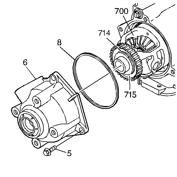
- Remove the case extension housing bolts (5).
- Remove the case extension housing (6) with the axle seal and the O-ring (8).

Installation Procedure
- Install the O-ring (8) to the case extension housing (6).
- Install the case extension housing (6) with the axle seal and the O-ring (8).
- Install the case extension housing bolts (5).
- Install the vehicle speed sensor. Refer to Vehicle Speed Sensor Replacement.
- Install the transaxle brace. Refer to Transmission Brace Replacement.
- Install the right drive axle to the transaxle. Refer to Wheel Drive Shaft Replacement.
- Lower the vehicle.
- Connect the negative battery cable. Refer to Battery Negative Cable Disconnection and Connection.
- Check and fill the transaxle as necessary.
- Inspect for fluid leaks.

Caution: Refer to Fastener Caution in the Preface section.
Tighten
Tighten the bolts to 36 N·m (27 lb ft).
Caution: Do NOT overfill the transaxle. The overfilling of the transaxle causes foaming, loss of fluid, shift complaints, and possible damage to the transaxle.
