For 1990-2009 cars only
Removal Procedure
- Disconnect the negative battery cable. Refer to Battery Negative Cable Disconnection and Connection.
- Raise and support the vehicle. Refer to Lifting and Jacking the Vehicle.
- Remove the crankshaft harmonic balancer. Refer to Crankshaft Balancer Replacement.
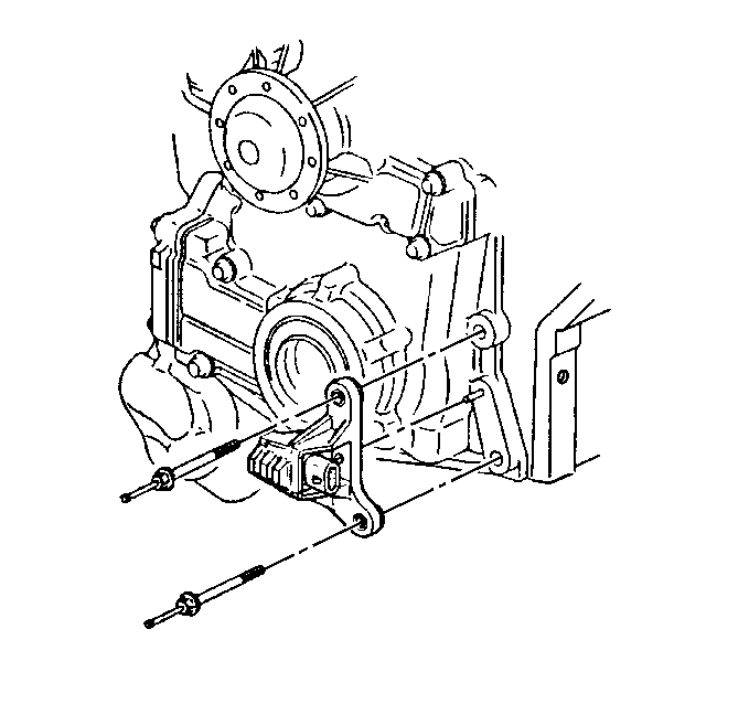
- Disconnect the crankshaft position (CKP) sensor electrical connector.
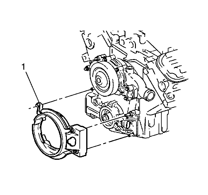
- Remove the CKP sensor shield (1). DO NOT use a pry bar.
- Remove the CKP sensor studs.
- Remove the CKP sensor.


Installation Procedure
- Install the CKP sensor.
- Install the CKP sensor studs.
- Install the CKP sensor shield (1).
- Connect the CKP sensor electrical connector.
- Install the crankshaft harmonic balancer. Refer to Crankshaft Balancer Replacement.
- Lower the vehicle.
- Connect the negative battery cable. Refer to Battery Negative Cable Disconnection and Connection.
- Perform the crankshaft position system variation learn procedure. Refer to Crankshaft Position System Variation Learn.

Caution: Refer to Fastener Caution in the Preface section.
Tighten
Tighten the studs to 30 N·m (22 lb ft).

