Diagnostic Instructions
| • | Perform the Diagnostic System Check - Vehicle prior to using this diagnostic procedure. |
| • | Review Strategy Based Diagnosis for an overview of the diagnostic approach. |
| • | Diagnostic Procedure Instructions provide an overview of each diagnostic category. |
DTC Descriptors
DTC P0107: Manifold Absolute Pressure (MAP) Sensor Circuit Low VoltageDTC P0108: Manifold Absolute Pressure (MAP) Sensor Circuit High Voltage
Diagnostic Fault Information
Circuit | Short to Ground | High Resistance | Open | Short to Voltage | Signal Performance |
|---|---|---|---|---|---|
5-Volt Reference | P0107, P0405, P0452, P0462, P0532, P0641 | P0106, P0107 | P0107 | P0108, P0453, P0533, P0641 | P0106, P0107 |
MAP Sensor Signal | P0107 | P0106, P0107 | P0107 | P0108 | P0106, P0107 |
Low Reference | -- | P0106, P0107 | P0106, P0108, P1101 | -- | P0106, P0108 |
Typical Scan Tool Data
Circuit | Short to Ground | Open | Short to Voltage |
|---|---|---|---|
Operating Conditions: Engine running, transmission in Park or Neutral Parameter Normal Range: 12-48 kPa (Varies with altitude) | |||
5-Volt Reference | 10 kPa | 10 kPa | 104 kPa |
MAP Sensor Signal | 10 kPa | 10 kPa | 104 kPa |
Low Reference | -- | 80-103 kPa | -- |
Circuit/System Description
The manifold absolute pressure (MAP) sensor has a 5-volt reference circuit, a low reference circuit, and a signal circuit. The powertrain control module (PCM) supplies 5 volts to the MAP sensor on a 5-volt reference circuit and provides a ground on a low reference circuit. The MAP sensor provides a voltage signal to the PCM on a signal circuit relative to the intake manifold pressure changes.
Conditions for Running the DTC
P0107
| • | DTCs P0068, P0120, P0220, P1516, P2101, P2108, P2120, P2125, P2135, or P2138 are not set |
| • | The ignition is ON. |
| • | The throttle angle is greater than 0 percent, if the engine speed is less than 1,000 RPM. |
| OR |
| • | The throttle angle is greater than 10 percent, if the engine speed is greater than 1,000 RPM. |
| • | The DTC runs continuously when the above conditions are met. |
P0108
| • | DTCs P0068, P0120, P0220, P1516, P2101, P2108, P2120, P2125, P2135, or P2138 are not set. |
| • | The engine has been running for a length of time that is determined by the startup coolant temperature. The length of time ranges from 5.5 minutes at less than -30°C (-22°F) to 10 seconds at more than +30°C (+86°F). |
| • | The throttle angle is less than 2 percent when the engine speed is less than 3,000 RPM. |
| OR |
| • | The throttle angle is more than 30 percent when the engine speed is greater than 3,000 RPM. |
| • | The DTC runs continuously when the above conditions are met. |
Conditions for Setting the DTC
P0107
| • | The control module detects that the MAP sensor voltage is less than 0.1 volt for more than 3 seconds. |
| • | This diagnostic runs continuously. |
P0108
| • | The control module detects that the MAP sensor voltage is more than 4.3 volts for more than 3 seconds. |
| • | This diagnostic runs continuously. |
Action Taken When the DTC Sets
DTCs P0107 and P0108 are Type B DTCs.
Conditions for Clearing the DTC
DTCs P0107 and P0108 are Type B DTCs.
Reference Information
Schematic Reference
Connector End View Reference
Electrical Information Reference
DTC Type Reference
Powertrain Diagnostic Trouble Code (DTC) Type Definitions
Scan Tool Reference
Control Module References for scan tool information
Special Tools
| • | J 23738-A Mityvac |
| • | J 35555 Metal Mityvac |
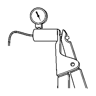
Circuit/System Testing
Important: All electrical components and accessories must be turned OFF, and allowed to power down.
- Ignition OFF, disconnect the harness connector at the MAP sensor.
- Ignition OFF for 90 seconds, test for less than 5 ohms between the low reference circuit terminal A and ground.
- Ignition ON, test for 4.8-5.2 volts between the 5-volt reference circuit terminal C and ground.
- Verify the scan tool MAP Sensor parameter is less than 12 kPa.
- Install a 3A fused jumper wire between the signal circuit terminal B and the 5-volt reference circuit terminal C. Verify the scan tool MAP Sensor parameter is greater than 103 kPa.
- If all circuits test normal, test or replace the MAP sensor.
| ⇒ | If greater than the specified range, test the low reference circuit for an open/high resistance. If the circuit tests normal, replace the PCM. |
| ⇒ | If less than the specified range, test the 5-volt reference circuit for a short to ground or an open/high resistance. If the circuit tests normal, replace the PCM. |
| ⇒ | If greater than the specified range, test the 5-volt reference circuit for a short to voltage. If the circuit tests normal, replace the PCM. |
| ⇒ | If greater than the specified range, test the signal circuit terminal B for a short to voltage. If the circuit tests normal, replace the PCM. |
| ⇒ | If less than the specified range, test the signal circuit for short to ground or an open/high resistance. If the circuit tests normal, replace the PCM. |
Component Testing
- Turn ON the ignition, with the engine OFF, and remove the MAP sensor.
- Install a 3A fused jumper wire between the 5-volt reference circuit terminal C and the corresponding terminal of the MAP sensor.
- Install a jumper wire between the low reference circuit terminal A of the MAP sensor and ground.
- Install a jumper wire at terminal B of the MAP sensor.
- Connect a DMM between the jumper wire from terminal B of the MAP sensor and ground.
- Install the J 23738-A or J 35555 to the MAP sensor vacuum port. Slowly apply vacuum to the sensor while observing the voltage on the DMM. The voltage should vary between 0-5.2 volts, without any spikes or dropouts.
| ⇒ | If the voltage is not within the specified range or is erratic, replace the MAP sensor. |
Repair Instructions
Perform the Diagnostic Repair Verification after completing the diagnostic procedure.
| • | Control Module References for PCM replacement, setup, and programming |
