Exhaust Manifold Replacement - Right Side 3.8L
Removal Procedure
- Remove the fuel injector sight shield. Refer to Fuel Injector Sight Shield Replacement .
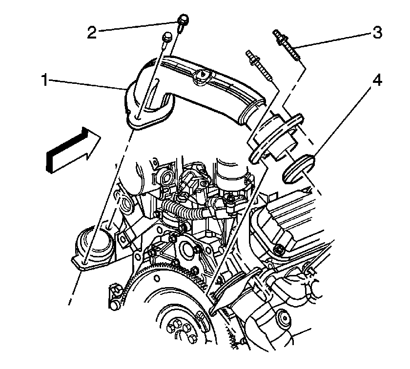
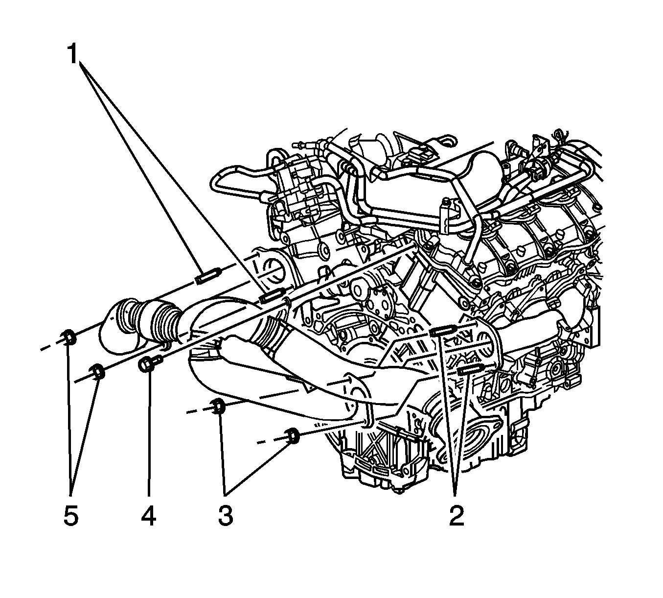
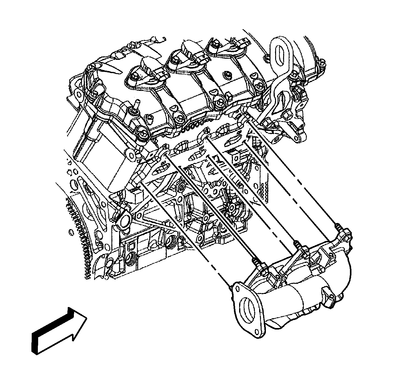
- Remove the exhaust crossover heat shield nuts (1).
- Remove the exhaust crossover heat shield (2).
- Remove the exhaust crossover pipe studs (3) from the right exhaust manifold.
- Raise and support the vehicle. Refer to Lifting and Jacking the Vehicle .
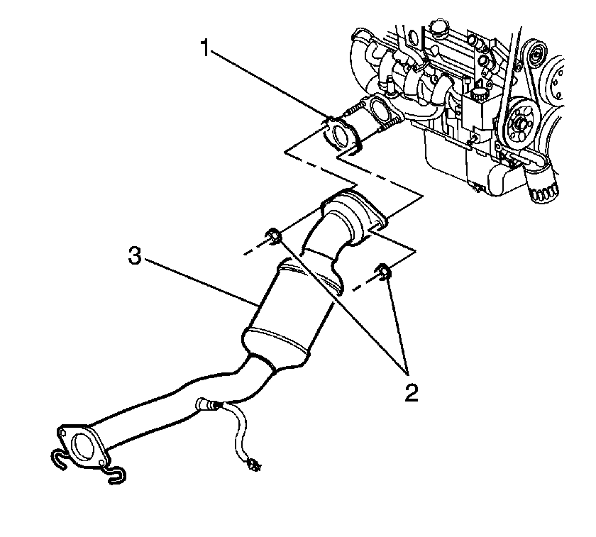
- Remove the exhaust manifold pipe stud nuts (2) and the catalytic converter pipe (3) from the right exhaust manifold.
- Lower the vehicle.
- Rotate the engine to access the right side of the engine. Refer to Rotating the Engine for Service Access .
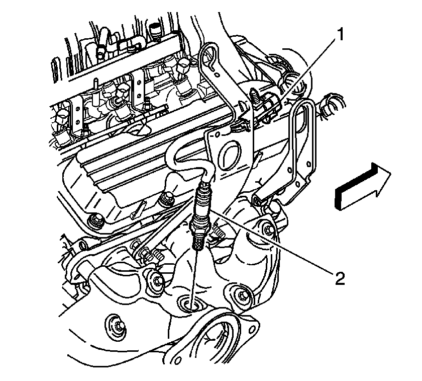
- Disconnect the heated oxygen sensor (HO2S) electrical connector (1).
- Remove the HO2S electrical connector (1) from the engine sight shield bracket.
- Remove the HO2S (2) from the right exhaust manifold. Refer to Heated Oxygen Sensor 1 Replacement .
- Remove the right side spark plugs from cylinders 2, 4 and 6. Refer to Spark Plug Replacement .
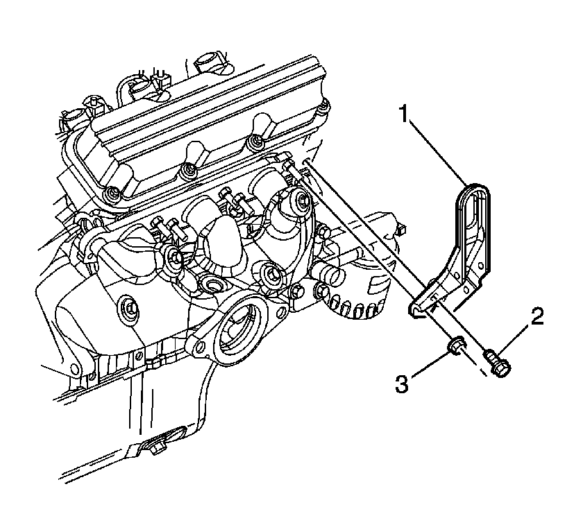
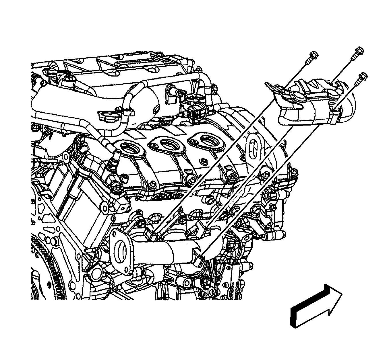
- Remove the fuel injector sight shield bracket nuts (2).
- Remove the fuel injector sight shield bracket (1).
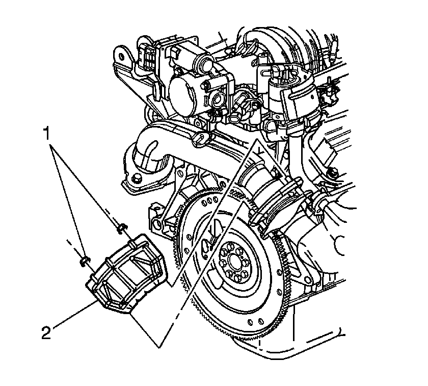
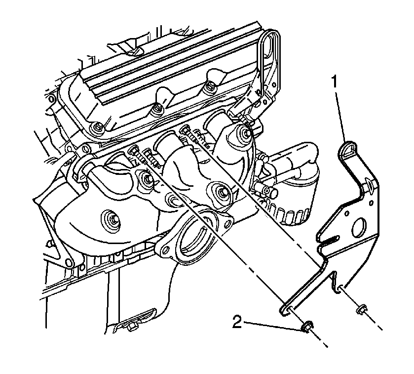
- Remove the right engine lift bracket bolt (2) and the nut (3).
- Remove the right engine lift bracket (1).
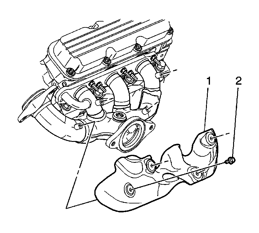
- Remove the right exhaust manifold heat shield bolts (2).
- Remove the right exhaust manifold heat shield (1).
- Raise the vehicle.
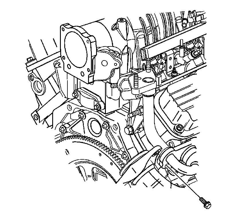
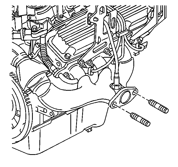
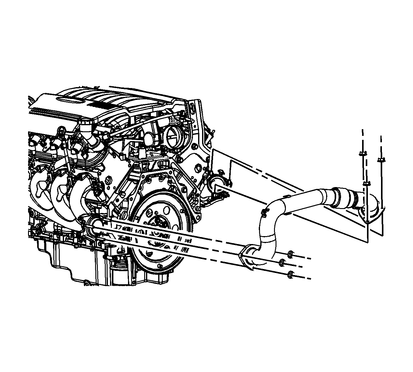
- Remove the exhaust gas recirculation (EGR) valve inlet adapter pipe bolt (1) from the right exhaust manifold.
- Lower the vehicle.
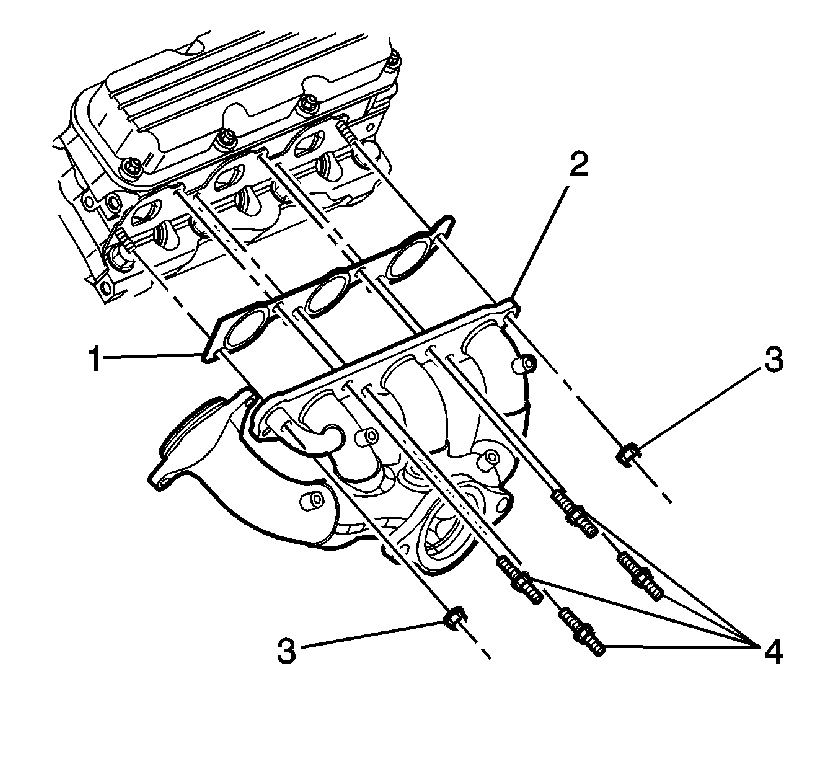
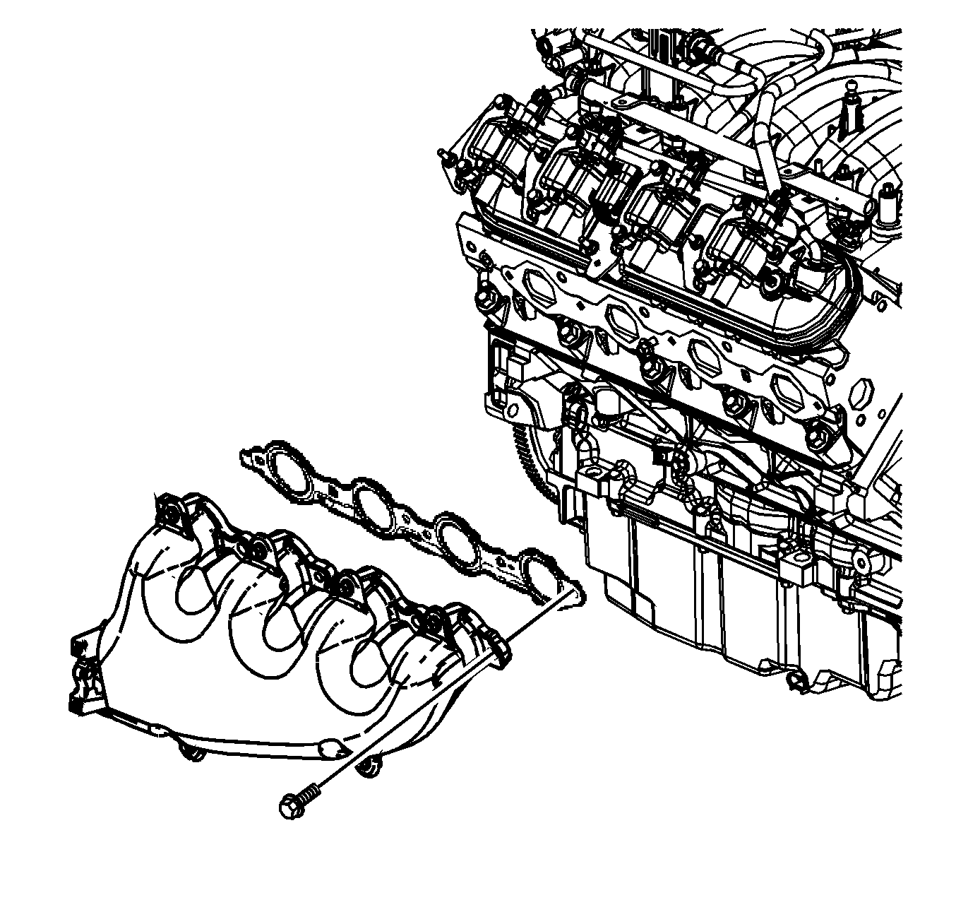
- Remove the right exhaust manifold studs (4) and the nuts (3).
- Remove the right exhaust manifold (2).
- Remove the right exhaust manifold gasket (1).
- Remove the exhaust manifold studs if damaged.
- Clean and Inspect the right exhaust manifold. Refer to Exhaust Manifold Cleaning and Inspection .
Installation Procedure
- Install the exhaust manifold studs if removed.
- Install the right exhaust manifold gasket (1).
- Install the right exhaust manifold (2).
- Install the right exhaust manifold studs (4) and the nuts (3).
- Raise the vehicle.
- Install the exhaust gas recirculation (EGR) valve inlet adapter pipe bolt (1) to the right exhaust manifold.
- Lower the vehicle.
- Install the right exhaust manifold heat shield (1).
- Install the right exhaust manifold heat shield bolts (2).
- Install the right engine lift bracket (1).
- Install the right engine lift bracket bolt (2) and the nut (3).
- Install the fuel injector sight shield bracket (1).
- Install the fuel injector sight shield bracket nuts (2).
- Install the right side spark plugs to cylinders 2, 4 and 6. Refer to Spark Plug Replacement .
- Install the HO2S (2) to the right exhaust manifold. Refer to Heated Oxygen Sensor 1 Replacement
- Install the HO2S electrical connector (1) to the engine sight shield bracket.
- Connect the HO2S electrical connector (1).
- Return the engine to the original position.
- Raise the vehicle.
- Install the catalytic converter pipe (3) to the right exhaust manifold.
- Install the catalytic converter pipe stud nuts (2) to the right exhaust manifold.
- Lower the vehicle.
- Install the exhaust crossover pipe studs (3) to the right exhaust manifold.
- Install the exhaust crossover heat shield (2).
- Install the exhaust crossover heat shield nuts (1).
- Install the engine mount struts. Refer to Engine Mount Strut Replacement - Right Side and Engine Mount Strut Replacement - Left Side .
- Install the fuel injector sight shield. Refer to Fuel Injector Sight Shield Replacement .
Notice: Use the correct fastener in the correct location. Replacement fasteners must be the correct part number for that application. Fasteners requiring replacement or fasteners requiring the use of thread locking compound or sealant are identified in the service procedure. Do not use paints, lubricants, or corrosion inhibitors on fasteners or fastener joint surfaces unless specified. These coatings affect fastener torque and joint clamping force and may damage the fastener. Use the correct tightening sequence and specifications when installing fasteners in order to avoid damage to parts and systems.
Tighten
Tighten the studs and the nuts to 30 N·m (22 lb ft).
Tighten
Tighten the bolt to 29 N·m (21 lb ft).
Tighten
Tighten the bolts to 10 N·m (89 lb in).
Tighten
Tighten the bolt and the nut to 30 N·m (22 lb ft).
Tighten
Tighten the nuts to 30 N·m (22 lb ft).
Tighten
Tighten the stud nuts to 35 N·m (26 lb ft).
Tighten
Tighten the studs to 20 N·m (15 lb ft).
Tighten
Tighten the nuts to 20 N·m (15 lb ft).
Exhaust Manifold Replacement - Right Side RPO LY7
Removal Procedure
- Remove the air inlet duct. Refer to Air Cleaner Inlet Duct Replacement .
- Remove the master cylinder fluid level sensor in order to provide clearance for lowering the powertrain. Refer to Brake Fluid Level Indicator Switch Replacement .
- Remove the engine mount struts. Refer to Engine Mount Strut Replacement - Left Side and Engine Mount Strut Replacement - Right Side .
- Raise and support the vehicle. Refer to Lifting and Jacking the Vehicle .
- Remove the catalytic converter. Refer to Catalytic Converter Replacement .
- Remove the exhaust crossover pipe to right bank exhaust manifold nuts (3).
- Remove the exhaust manifold bolts.
- Remove the exhaust manifold.
- Remove and discard the exhaust manifold gasket.
- If replacing the exhaust manifold, remove the exhaust manifold heat shield bolts and the heat shield.
- Clean the exhaust manifold sealing surfaces.
Important: Use a long extension in order to remove the exhaust crossover pipe nuts.
Installation Procedure
- If the exhaust manifold was replaced, position the exhaust manifold heat shield to the exhaust manifold.
- Install the exhaust manifold heat shield bolts.
- Insert one bolt through a bolt hole in the exhaust manifold.
- Position the NEW exhaust manifold gasket over the bolt.
- Position the exhaust manifold to the cylinder head.
- Tighten the bolt until snug.
- Install the remaining exhaust manifold bolts.
- Install the exhaust crossover pipe to right bank exhaust manifold nuts (3).
- Install the catalytic converter. Refer to Catalytic Converter Replacement .
- Connect the intermediate steering shaft to the steering gear. Refer to Intermediate Steering Shaft Replacement .
- Lower the vehicle.
- Install the engine mount struts. Refer to Engine Mount Strut Replacement - Left Side and Engine Mount Strut Replacement - Right Side .
- Install the master cylinder fluid level sensor. Refer to Brake Fluid Level Indicator Switch Replacement .
- Install the air inlet duct. Refer to Air Cleaner Inlet Duct Replacement .
Notice: Refer to Fastener Notice in the Preface section.
Tighten
Tighten the bolts to 10 N·m (89 lb in).
Tighten
Tighten the bolts to 20 N·m (15 lb ft).
Tighten
Tighten the bolts to 34 N·m (25 lb ft).
Exhaust Manifold Replacement - Right Side RPO LS4
Removal Procedure
- Remove the engine sight shield. Refer to Upper Intake Manifold Sight Shield Replacement.
- Remove the spark plugs. Refer to Spark Plug Replacement .
- Remove the exhaust crossover pipe nuts from the right exhaust manifold.
- Disconnect the catalytic converter from the exhaust manifold. Refer to Catalytic Converter Replacement .
- Support the catalytic convertor and exhaust system with the mechanics wire.
- Lower the vehicle.
- Remove the ignition coil. Refer to Ignition Coil Replacement .
- Remove the heated oxygen sensor (HO2S). Refer to Heated Oxygen Sensor Replacement - Bank 1 Sensor 1 .
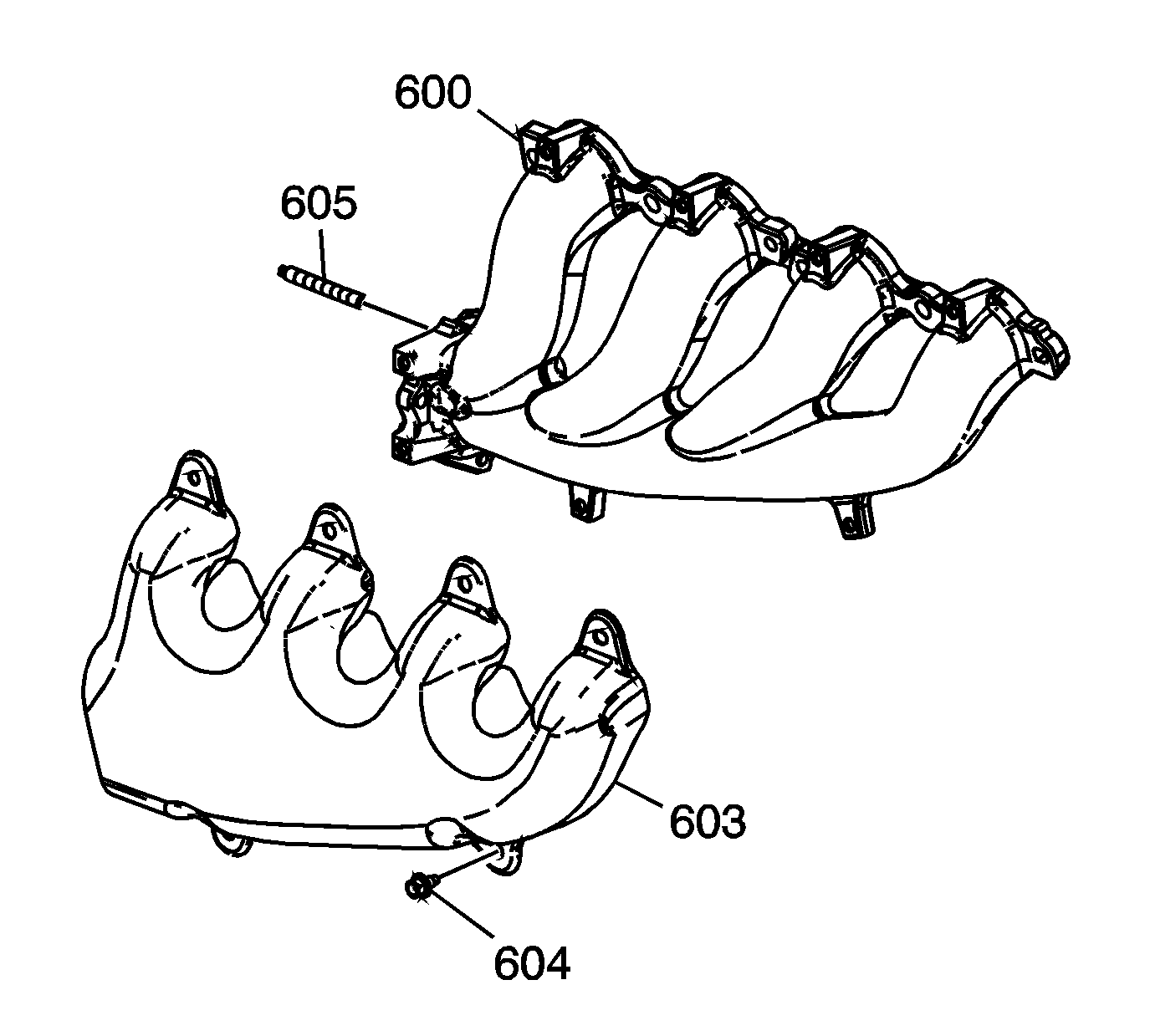
- Remove the exhaust manifold heat shield bolts (604).
- Remove the exhaust manifold heat shield (603).
- Remove the exhaust manifold bolts.
- Remove the exhaust manifold.
- Remove and discard the exhaust manifold gasket.
Installation Procedure
Important:
• Tighten the exhaust manifold bolts as specified in the service procedure. Improperly installed and/or leaking exhaust manifold gaskets my affect vehicle emissions and/or On Board Diagnostic (OBD) II system performance. • The cylinder head exhaust manifold bolt hole threads must be clean and free of debris or threadlocking material. • DO NOT apply threadlock to the first three thread of the bolts.
- Apply a 5 mm (0.2 in) wide band of threadlock GM P/N 12345493 (Canadian P/N 10953488) or equivalent to the threads of the exhaust manifold bolts.
- Install a NEW exhaust manifold gasket, the exhaust manifold and bolts.
- Using a flat punch, bend over the exposed edge of the exhaust manifold gasket at the rear of the right cylinder head.
- Install the exhaust manifold heat shield (603).
- Install the exhaust manifold heat shield bolts (604).
- Install the O2 sensor. Refer to Spark Plug Replacement.
- Raise the vehicle.
- Remove the mechanics wire from the exhaust system and connect the catalytic converter. Refer to Catalytic Converter Replacement .
- Install the exhaust crossover pipe nuts to the right exhaust manifold.
- Install the ignition coil. Refer to Ignition Coil Replacement .
- Install the spark plugs. Refer to Spark Plug Replacement .
- Install the fuel injector sight shield. Refer to Upper Intake Manifold Sight Shield Replacement .
Notice: Refer to Fastener Notice in the Preface section.
Tighten
| • | Tighten the bolts a first pass to 15 N·m (11 lb ft). Tighten the bolts beginning with the center 2 bolts. Alternate from side to side, and work toward the outside. |
| • | Tighten the bolts a final pass to 20 N·m (15 lb ft). Tighten the bolts beginning with the center 2 bolts. Alternate from side to side, and work toward the outside. |
Tighten
Tighten the bolts to 9 N·m (80 lb in).
Tighten
Tighten the nuts to 25 N·m (18 lb ft).
