Removal Procedure
- Raise and support the vehicle. Refer to Lifting and Jacking the Vehicle .
- Place a drain pan under the vehicle.
- Remove the tire and wheel assemblies. Refer to Tire and Wheel Removal and Installation .
- Disconnect the snaps (3) from the power steering heat shield (2).
- Remove the power steering heat shield (2) from the power steering gear (1).
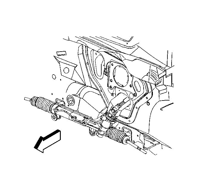
- Disconnect the intermediate steering shaft from the steering gear. Refer to Intermediate Steering Shaft Replacement .
- Disconnect both outer tie rod ends from the steering knuckles. Refer to Rack and Pinion Outer Tie Rod End Replacement .
- Disconnect the stabilizer shaft from the frame to allow bolt access. Refer to Stabilizer Shaft Insulator Replacement .
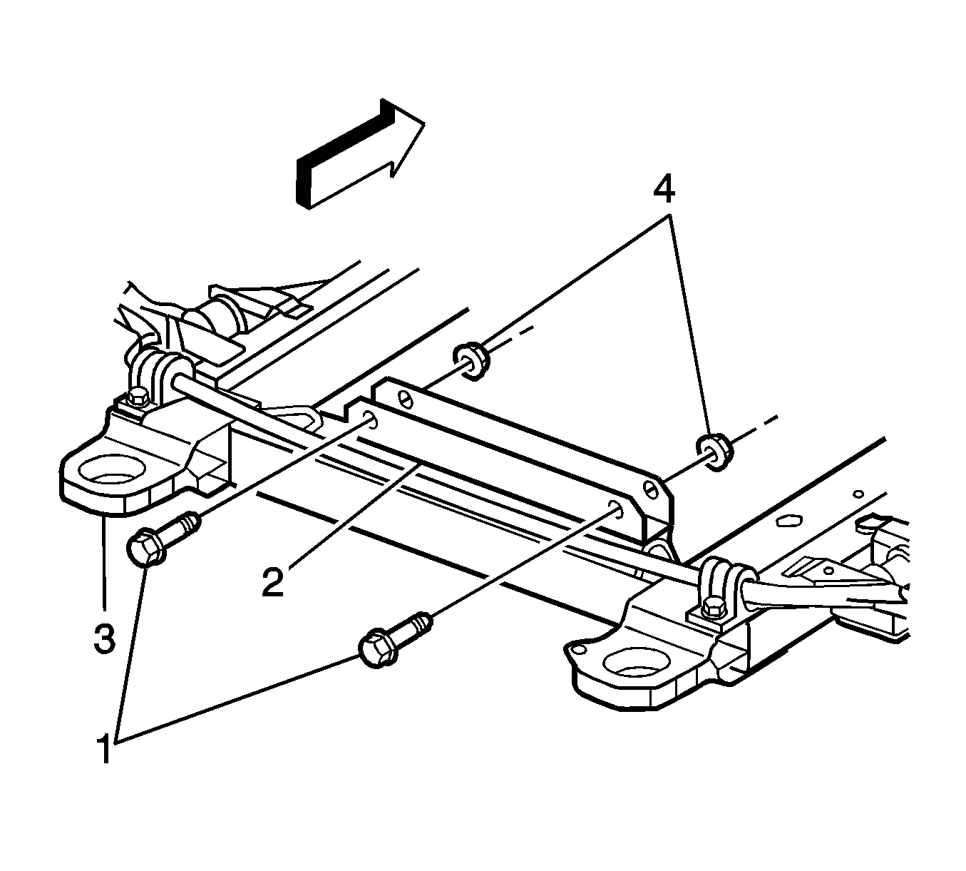
- Support the rear of the frame (3) using jackstands.
- Remove the frame bolts from the rear of the frame. Refer to Frame Replacement .
- Lower the rear of the frame (3).
- Disconnect the power steering pressure hose from the power steering gear. Refer to Power Steering Pressure Pipe/Hose Replacement .
- Disconnect the power steering return hose from the power steering gear. Refer to Power Steering Cooler Pipe/Hose Replacement .
- If applicable, disconnect the Magnasteer Variable Assist harness connector from the power steering gear assembly.
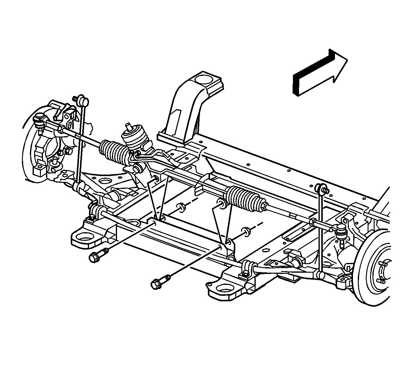
- Remove the power steering gear mounting bolts and nuts (1, 4).
- Remove the power steering gear through the left wheel opening.


Caution: Failure to disconnect the intermediate shaft from the rack and pinion stub shaft can result in damage to the steering gear and/or intermediate shaft. This damage can cause loss of steering control which could result in personal injury.
Notice: Set steering shaft so the block tooth on the upper steering shaft is at the 12 o'clock position, the wheels on the vehicle are straight ahead and set the ignition switch to the LOCK position. Failure to follow these procedures could result in damage to the coil.

Important: The power steering gear mounting bolts are different sizes. Note each bolt location for assembly.
Notice: Do not lower the rear of the frame too far as damage to the engine components nearest to the cowl may result.

Installation Procedure
- Install the power steering gear through the left wheel opening.
- Install the power steering gear mounting bolts and nuts as previously noted.
- Inspect the threads on the power steering pressure hose and the power steering return hose.
- Inspect the O-ring seals on the power steering hoses.
- Replace the seals if damaged, lubricate the seals before installation.
- Install the clamp that holds the power steering hoses to the power steering gear.
- If applicable, connect the Magnasteer Variable Assist harness connector to the power steering gear assembly.
- Connect the power steering pressure hose to the power steering gear. Refer to Power Steering Pressure Pipe/Hose Replacement .
- Connect the power steering return hose to the power steering gear. Refer to Power Steering Cooler Pipe/Hose Replacement .
- Raise the frame into position (3).
- Install the rear frame bolts. Refer to Frame Replacement .
- Remove the jackstands.
- Connect the tie rod ends to the steering knuckles. Refer to Rack and Pinion Outer Tie Rod End Replacement .
- Connect the stabilizer shaft to the frame. Refer to Stabilizer Shaft Insulator Replacement .
- Connect the intermediate steering shaft to the steering gear. Refer to Intermediate Steering Shaft Replacement .
- Install the power steering heat shield (2) to the steering gear (1).
- Connect the snaps (3) on the power steering heat shield (2).
- Install the tire and wheel assemblies. Refer to Tire and Wheel Removal and Installation .
- Remove the drain pan from under the vehicle.
- Lower the vehicle.
- Fill the power steering system with power steering fluid. Refer to Checking and Adding Power Steering Fluid .
- Bleed the power steering system. Refer to Power Steering System Bleeding .
- Inspect the power steering system for leaks. Refer to Power Steering Fluid Leaks .
- Perform a front end alignment. Refer to Wheel Alignment Measurement .

Notice: Refer to Fastener Notice in the Preface section.

Tighten
Tighten both (M12) bolts to 60 N·m (42 lb ft) plus 180 degrees.

Notice: Set steering shaft so the block tooth on the upper steering shaft is at the 12 o'clock position, the wheels on the vehicle are straight ahead and set the ignition switch to the LOCK position. Failure to follow these procedures could result in damage to the coil.
Important: During the installation of the intermediate steering shaft, ensure the steering shaft is seated before you install the pinch bolt. The two mating shafts may disengage if the pinch bolt is inserted into the coupling before the steering shaft installation.

