Refer to Engine Controls Schematics
Engine Data Sensors, MAF and EGR
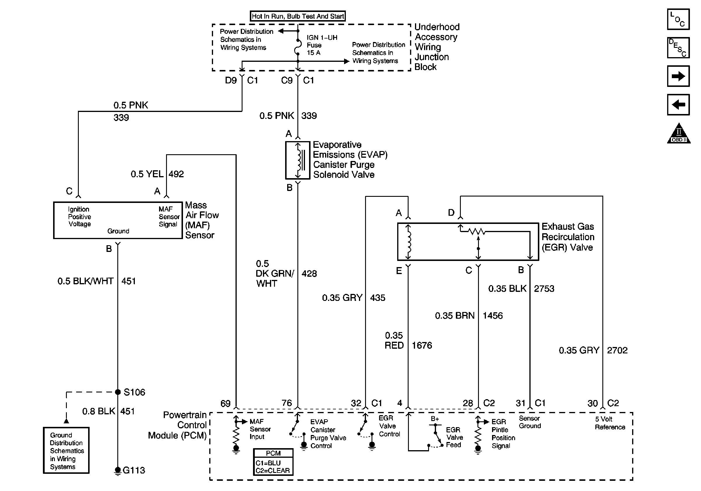
.
Circuit Description
The powertrain control module (PCM) monitors the exhaust gas recirculation (EGR) valve pintle position input to ensure that the valve responds properly to commands from the PCM. The linear EGR valve is controlled by using an ignition positive driver and ground circuit within the PCM. The driver has the ability to detect an electrical malfunction in the ignition positive or ground circuit. If an electrical malfunction occurs, the driver signals the PCM to set DTC P0403.
Conditions for Running the DTC
The engine is cranking or running.
Conditions for Setting the DTC
| • | The PCM detects an electrical malfunction in the control circuit for the EGR valve. |
| • | The condition is present for more than 20 seconds. |
Action Taken When the DTC Sets
| • | The PCM will illuminate the malfunction indicator lamp (MIL) during the second consecutive trip in which the diagnostic test has been run and failed. |
| • | The PCM will store conditions which were present when the DTC set as Freeze Frame/Failure Records data. |
Conditions for Clearing the MIL/DTC
| • | The PCM will turn OFF the malfunction indicator lamp (MIL) during the third consecutive trip in which the diagnostic has run and passed. |
| • | The history DTC will clear after 40 consecutive warm-up cycles have occurred without a malfunction. |
| • | The DTC can be cleared by using a scan tool. |
Diagnostic Aids
| • | Poor connection at the PCM or EGR valve--Inspect harness connectors for: |
| - | Backed out terminals |
| - | Improper mating |
| - | Broken locks |
| - | Improperly formed or damaged terminals |
| - | Poor terminal to wire connection |
| • | Damaged harness--Inspect the wiring harness for damage. If the harness appears to be OK, with a DMM, check circuit continuity while moving connectors and wiring harnesses related to the EGR valve. A change in the display will indicate the location of the malfunction. |
Test Description
The numbers below refer to the step numbers on the diagnostic table.
-
Listen for an audible click when the solenoid operates. Command the EGR between 0 percent to 10 percent. Repeat the commands as necessary.
-
Verifies that the PCM is providing voltage to the solenoid.
-
Tests for an open in the ground circuit to the solenoid.
-
Tests if voltage is constantly being applied to the solenoid.
-
The PCM utilizes electrically erasable programmable read only memory (EEPROM). When the PCM is replaced, the new PCM must be programmed.
Step | Action | Values | Yes | No |
|---|---|---|---|---|
1 | Did you perform the Powertrain On-Board Diagnostic (OBD) System Check? | -- | Go to Step 2 | |
Does the solenoid turn ON and OFF with each command? | -- | Go to Diagnostic Aids | Go to Step 3 | |
Does the test lamp turn ON and OFF with each command? | -- | Go to Step 4 | Go to Step 5 | |
Does the test lamp turn ON and OFF with each command? | -- | Go to Step 8 | Go to Step 10 | |
Does the test lamp remain illuminated with each command? | -- | Go to Step 7 | Go to Step 6 | |
6 | Test the control circuit of the solenoid for a short to ground or an open. Refer to Wiring Repairs in Wiring Systems. Did you find and correct the condition? | -- | Go to Step 13 | Go to Step 9 |
7 | Test the control circuit of the solenoid for a short to voltage. Refer to Wiring Repairs in Wiring Systems. Did you find and correct the condition? | -- | Go to Step 13 | Go to Step 9 |
8 | Inspect for poor connections at the EGR. Refer to Testing for Intermittent Conditions and Poor Connections and Connector Repairs in Wiring systems. Did you find and correct the condition? | -- | Go to Step 13 | Go to Step 11 |
9 | Inspect for poor connections at the PCM. Refer to Testing for Intermittent Conditions and Poor Connections and Connector Repairs in Wiring Systems. Did you find and correct the condition? | -- | Go to Step 13 | Go to Step 12 |
10 | Repair the ground circuit of the solenoid. Refer to Wiring Repairs in Wiring Systems. Did you complete the repair? | -- | Go to Step 13 | -- |
11 | Replace the EGR valve. Did you complete the replacement? | -- | Go to Step 13 | -- |
|
Important: The replacement PCM must be programmed. Replace the PCM. Refer to Powertrain Control Module Replacement/Programming . Did you complete the replacement? | -- | Go to Step 13 | -- | |
13 |
Does the DTC reset? | -- | Go to Step 2 | System OK |
