Special Tools
| • | EN 46116 Valve Stem Seal Remover/Installer |
| • | EN 46117 Valve Stem Key Remover/Installer |
| • | EN 46119 Off-Vehicle Valve Spring Compressor Adapter |
| • | EN-46122 Camshaft Position Actuator Check-Ball Valve Remover/Installer |
| • | J 8062 Valve Spring Compressor - Head Off |
| • | J 2619-01 Slide Hammer |
| • | J-37281-A Injector Remover |
| For equivalent regional tools, refer to Special Tools. |
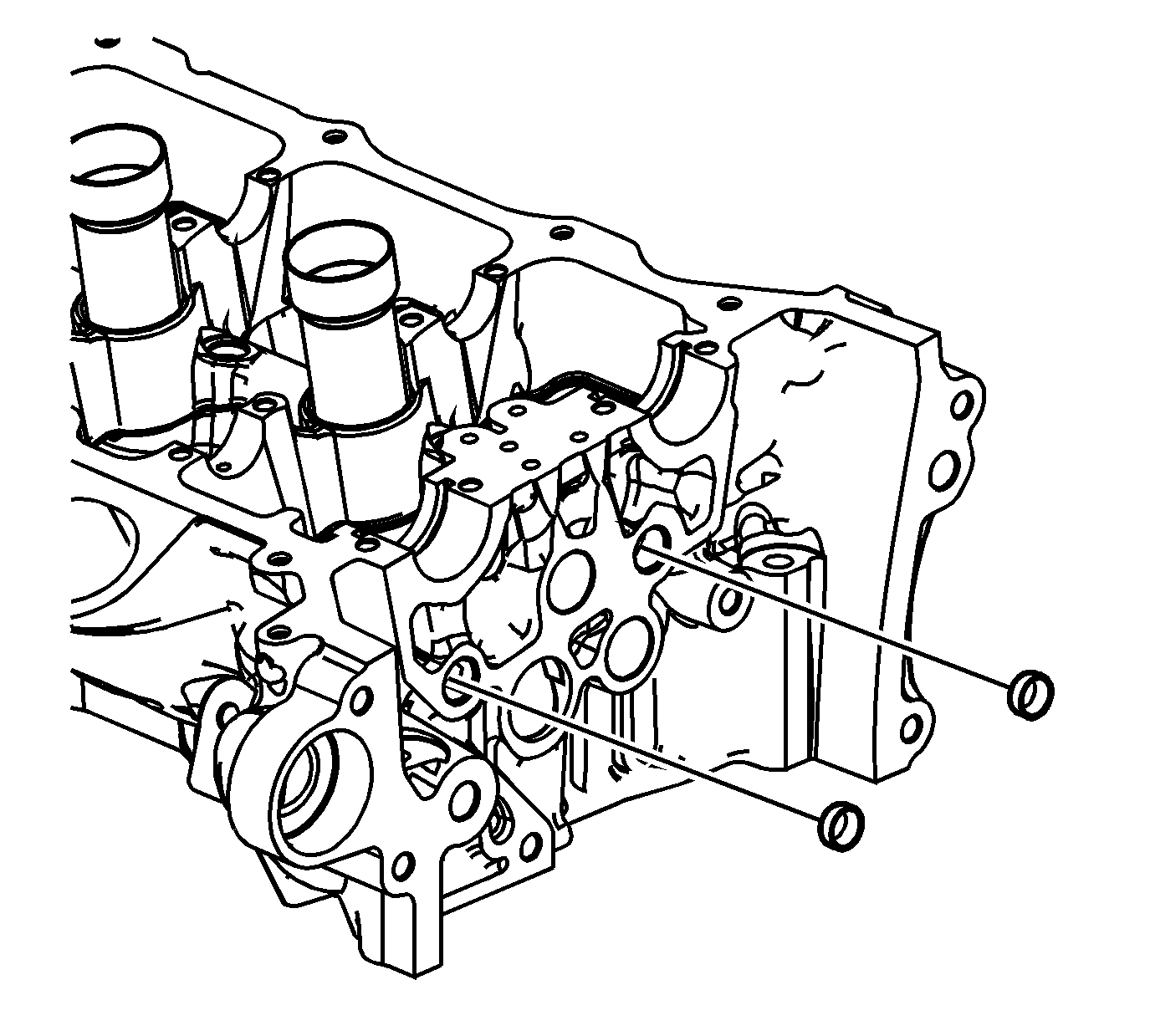
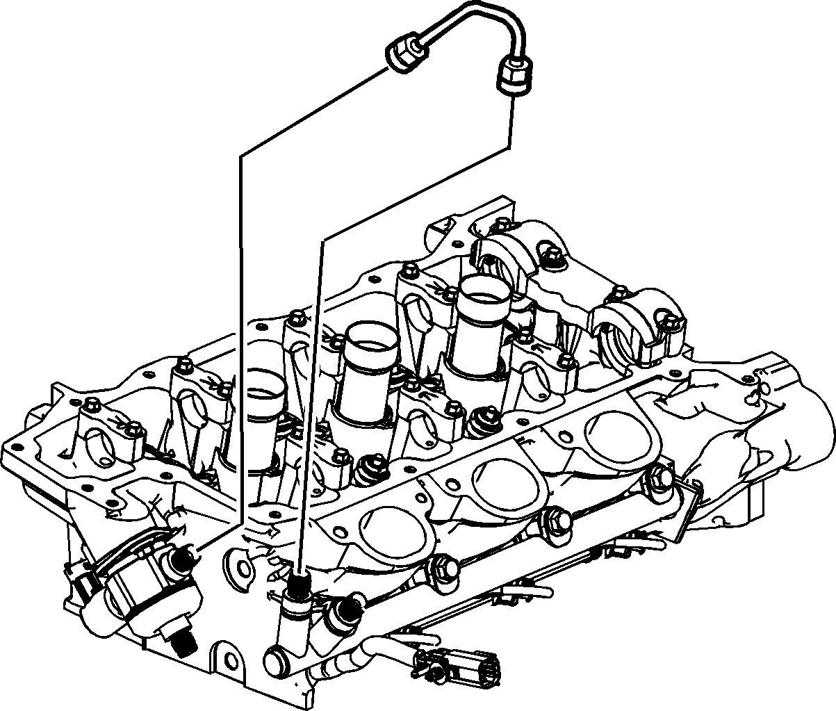
- Remove and discard high pressure fuel line. - LH Cylinder Head
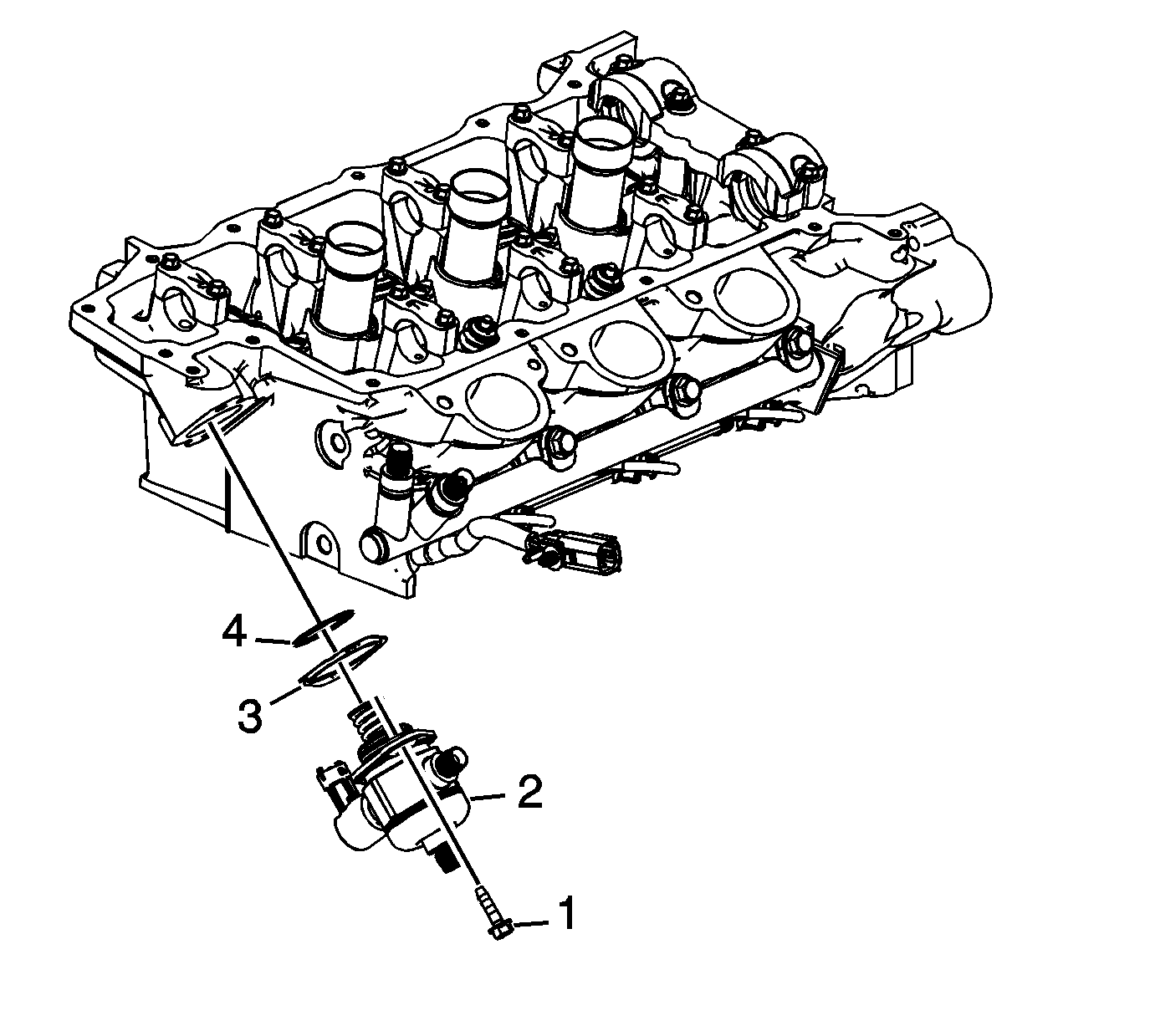
- Remove and discard high pressure fuel pump bolts (1). - LH Cylinder Head
- Remove the high pressure fuel pump (2). - LH Cylinder Head
- Remove and discard the high pressure fuel pump gasket (3). - LH Cylinder Head
- Remove and discard the high pressure fuel pump O-ring (4). - LH Cylinder Head
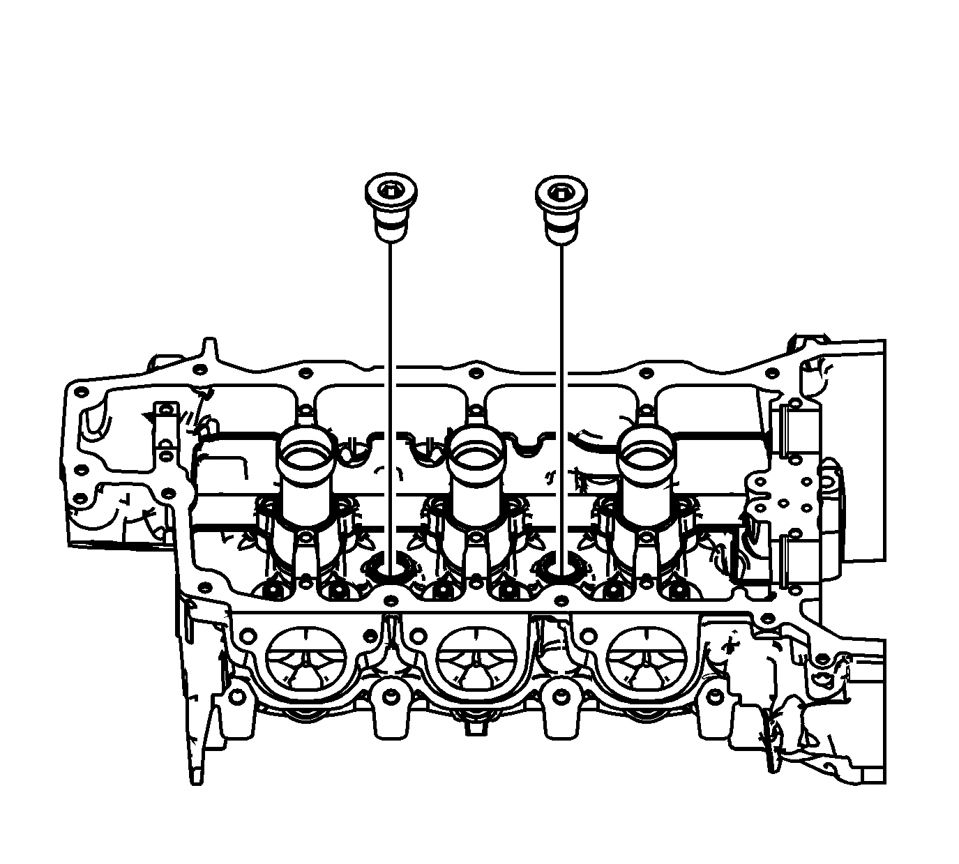
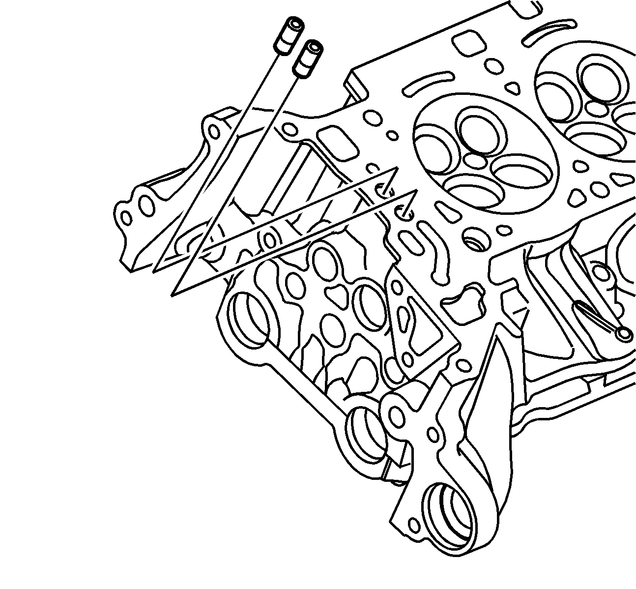
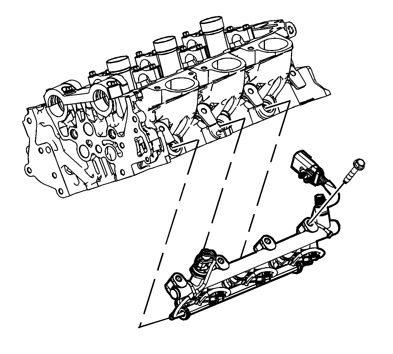
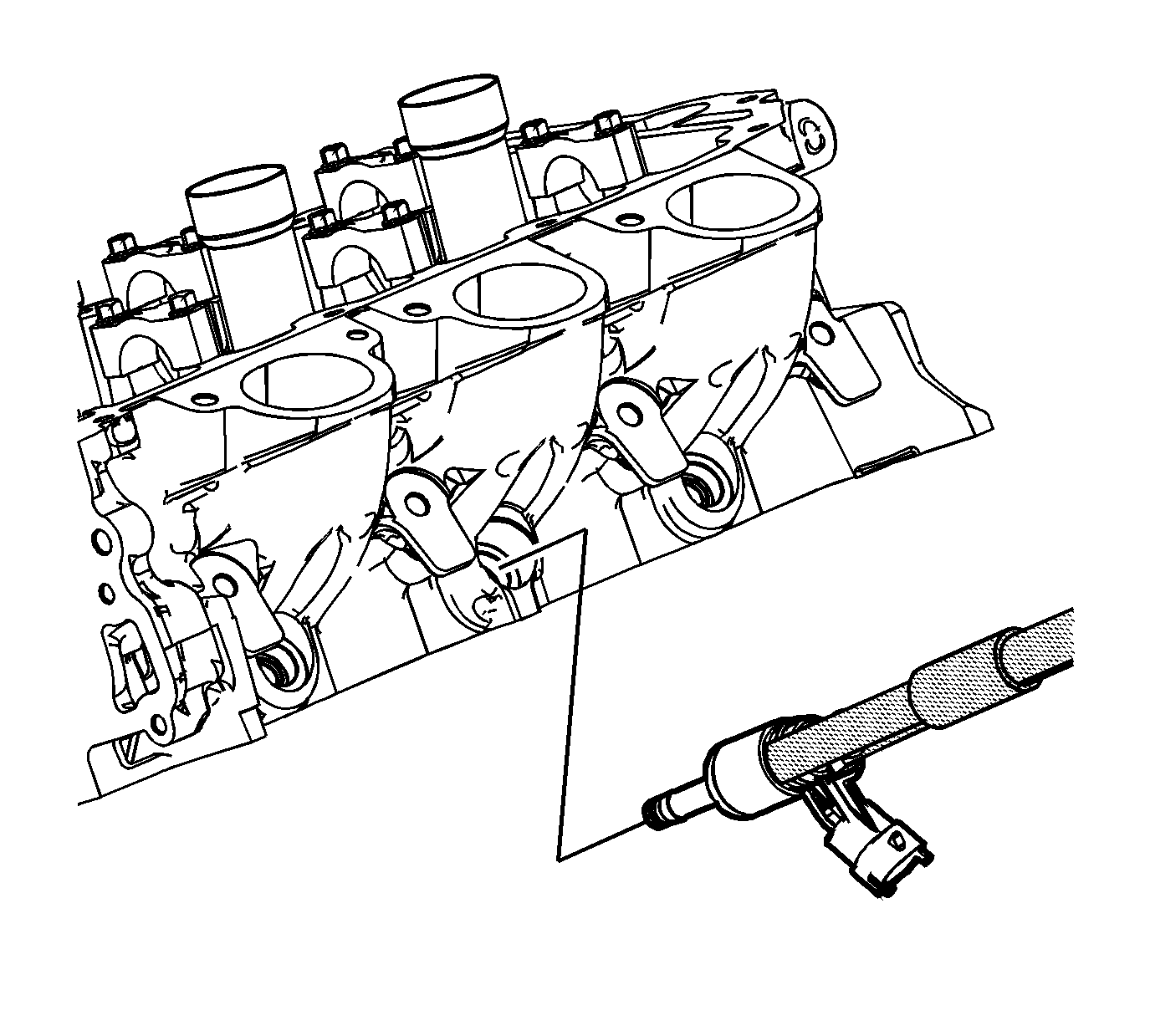
- Remove the fuel rail bolts.
- Remove the fuel rail and injectors.
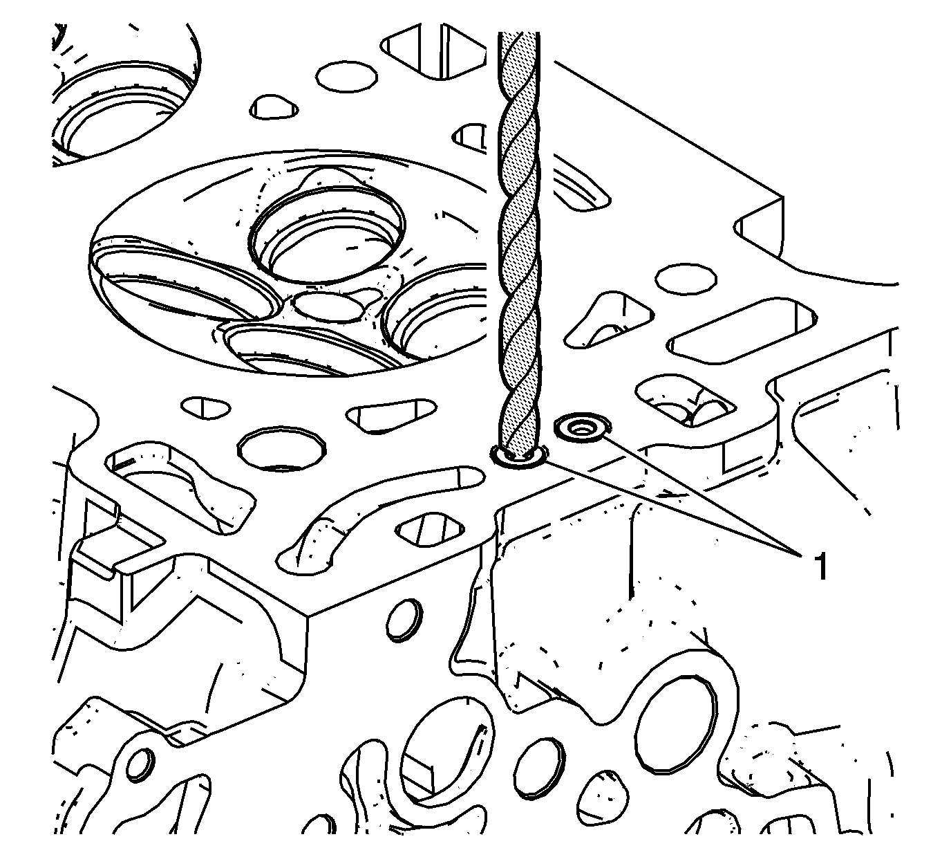
- The injectors may stay in the cylinder head. Remove the fuel injector hold-down clamp before removing the injector.
- Use the J-37281-A remover and the J 2619-01 slide hammer to remove the injector.
- Remove the engine coolant temperature (ECT) sensor. - LH Cylinder Head
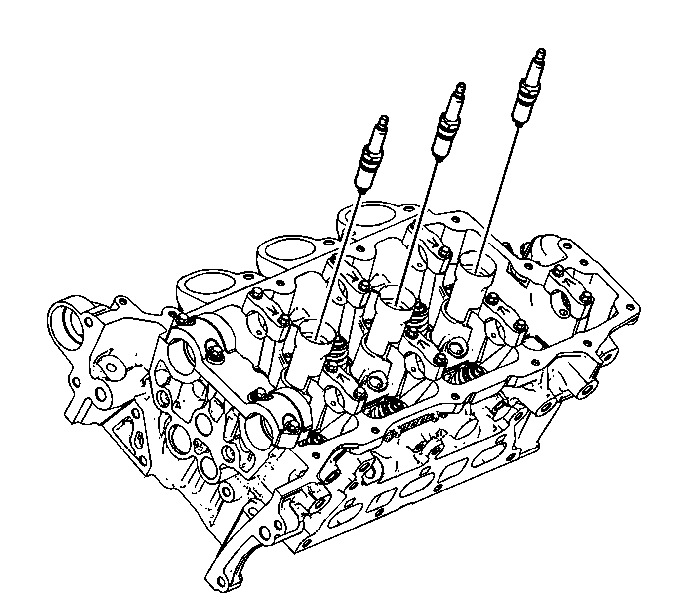
- Remove the spark plugs.
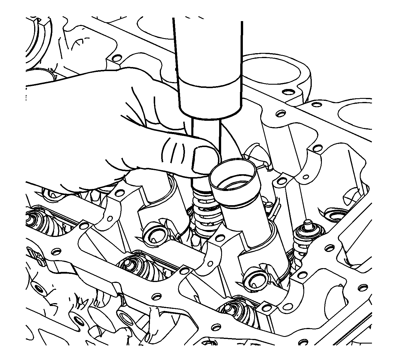
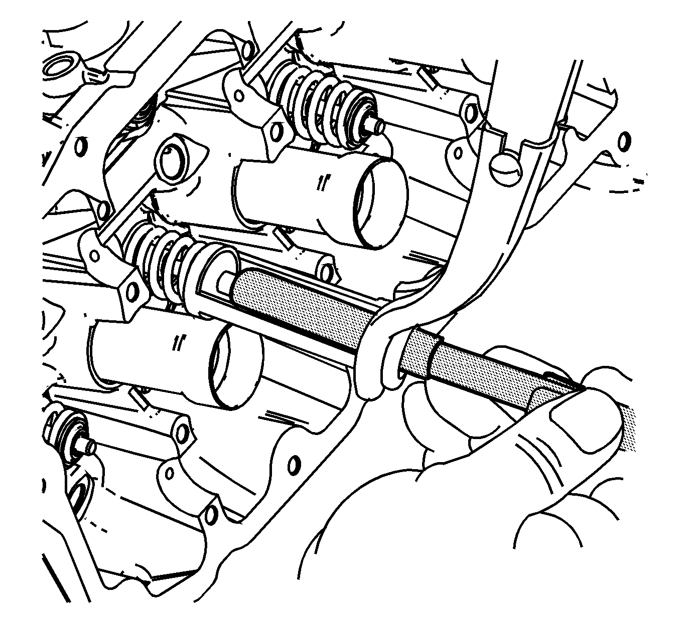
- Using an appropriately sized deep socket and a plastic hammer, lightly tap on the valve spring retainer to loosen the valve keepers.
- Compress the valve spring using the J 8062 compressor and the EN 46119 adapter .
- Use the magnet of the EN 46117 remover/installer in order to remove the valve keepers.
- Remove the valve spring compressor and the adapter.
- Remove the valve spring retainer.
- Remove the valve spring.
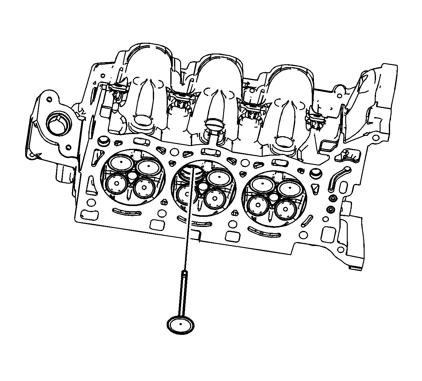
- Remove the valve.
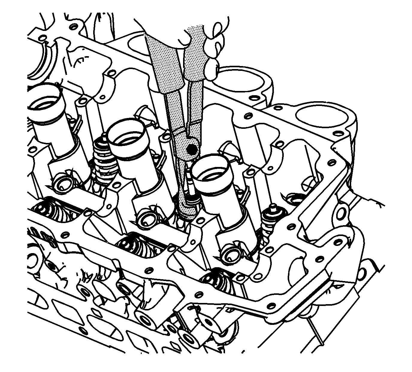
- Remove the valve stem oil seal using the EN 46116 remover/installer and discard.
- Repeat these procedures for the remaining valves.
- Remove the cylinder head oil gallery expansion plugs.
- Remove the cylinder head coolant threaded plugs.
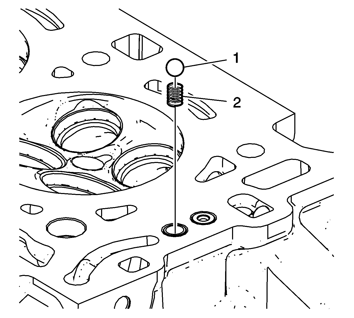
- Inspect the camshaft position actuator oil feed check valves. Damaged, restricted or clogged check valves must be replaced.
- Place cylinder head on firm surface with check valves (1) facing up. Protect all cylinder head components and machined surfaces.
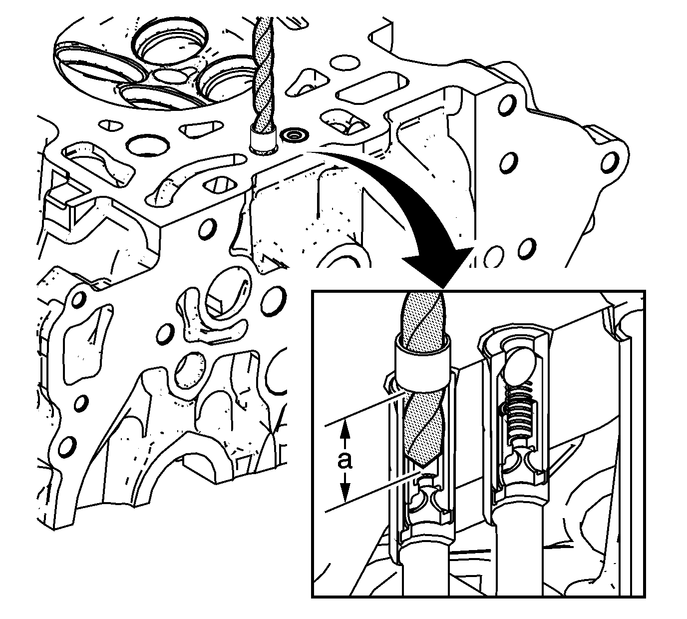
- Using drill bit EN-46122-3, drill out top portion of check valve to expose internal check ball.
- Remove check ball (1) and check ball spring (2) from inside of check valve.
- Continue drilling remainder of check valve sleeve to a depth of approximately 19 mm (0.75 in) (a) by placing tape on drill bit as a depth gauge. It is not necessary or desirable to drill completely through the bottom of the check valve.
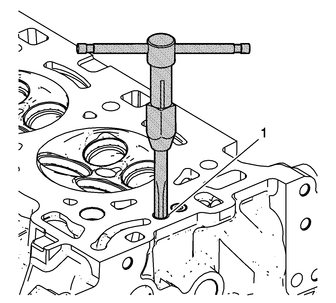
- Lubricate tap EN-46122-4 with lubricant included in EN-46122 remover/installer . Tap drilled out portion of check valve (1) remaining in cylinder head. Tap to full depth possible until tap bottoms out in head.
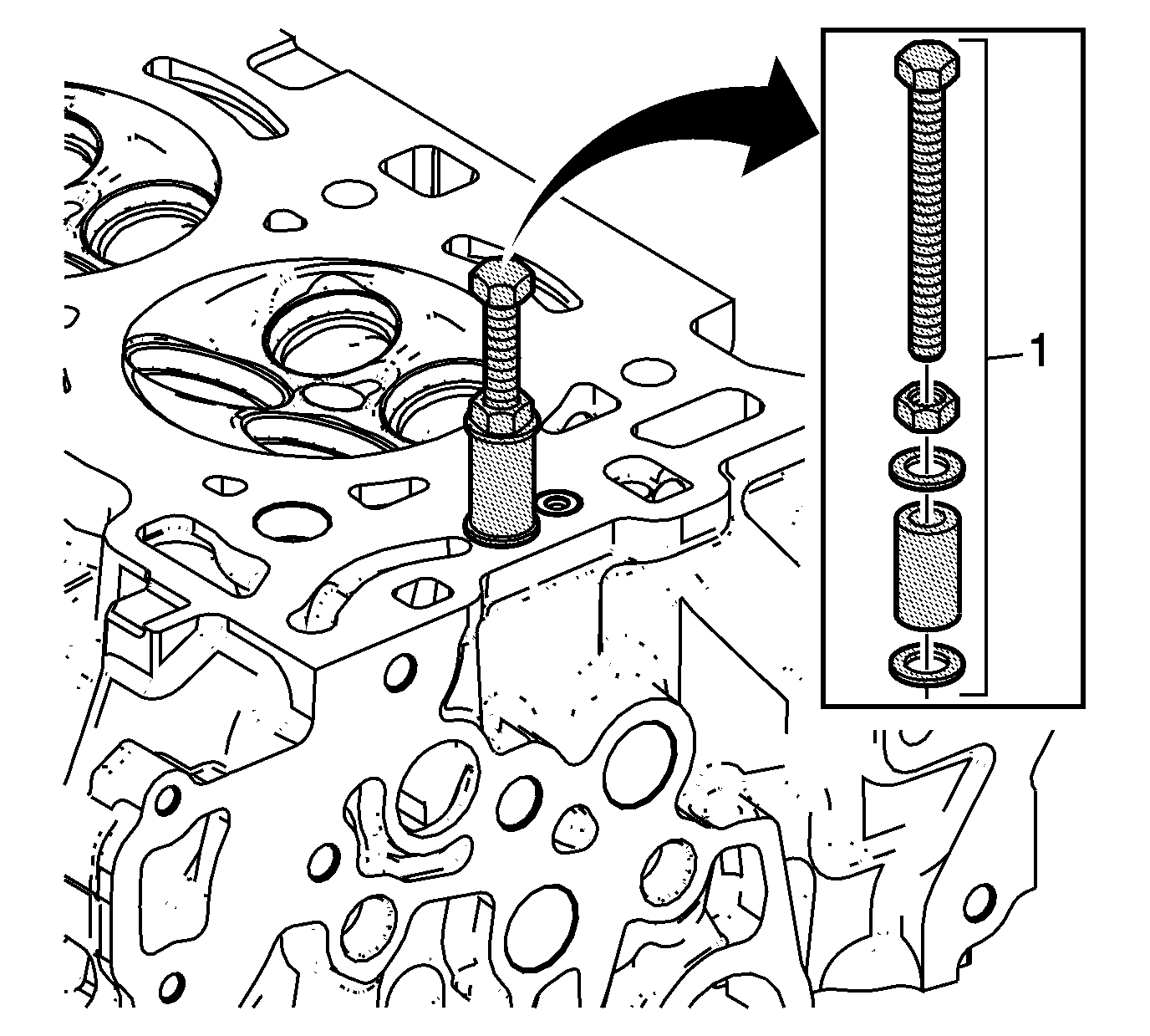
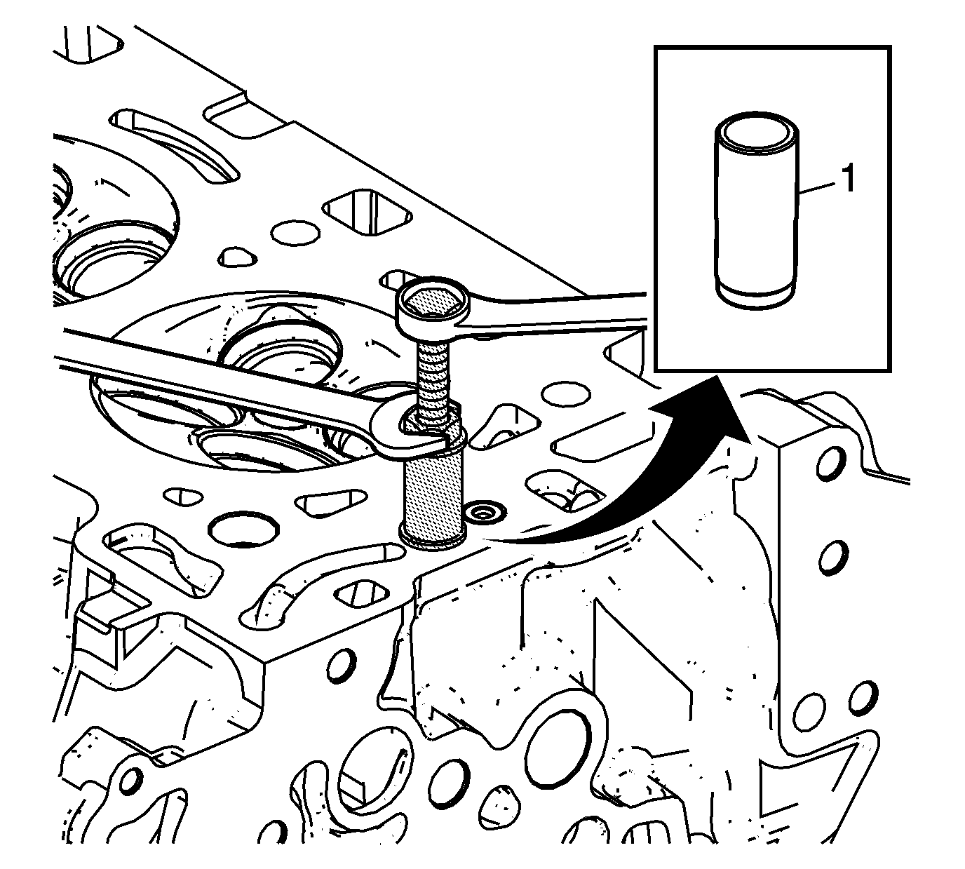
- Assemble bolt, nut, washers, and collar EN-46122-2 (1) as shown. Position collar with slightly-larger inside diameter DOWN toward the cylinder head.
- Screw bolt by hand fully down into threaded check valve sleeve, then lightly tighten nut against washer.
- Hold bolt with one wrench, and use another to tighten the nut until the check valve sleeve (1) is removed from the cylinder head.
- Clean check valve bore and related passages thoroughly to remove any drilling chips or other debris.

Note: Ensure valve heads will not contact anything during the following step in order to avoid bending or damage.
Warning: Compressed valve springs have high tension against the valve spring compressor. Valve springs that are not properly compressed by or released from the valve spring compressor can be ejected from the valve spring compressor with intense force. Use care when compressing or releasing the valve spring with the valve spring compressor and when removing or installing the valve stem keys. Failing to use care may cause personal injury.
Caution: Do not compress the valve springs less than 24.0 mm (0.943 in). Contact between the valve spring retainer and the valve stem oil seal can cause potential valve stem oil seal damage.

Note: NEVER reuse a valve stem oil seal.