Removal Procedure
Notice: To prevent equipment damage, never connect or disconnect the wiring harness connection from the EBCM with the ignition switch in the ON position.
- Turn the ignition switch to the OFF position.
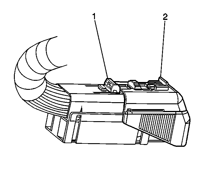
- Remove red locking tab from connector lock tab (1).
- Push down lock tab (1) and then move sliding connector cover (2) to the open position.
- Disconnect the EBCM/EBTCM harness connector.
- Brush off any dirt/debris that has accumulated on the assembly.
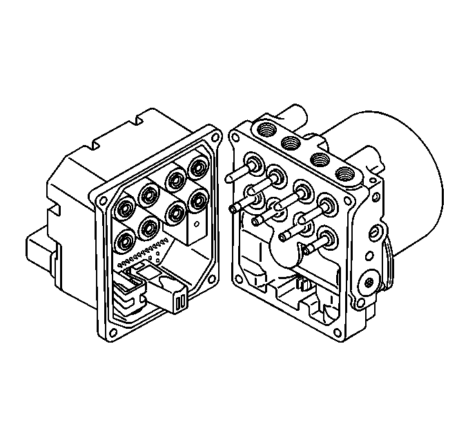
- Remove the four EBCM/EBTCM to BPMV screws (1).
- Separate the EBCM/EBTCM (2) from the BPMV (3) by gently pulling apart until separated.


Important: Do not pry apart using a tool. Be careful not to damage BPMV surface.
Important: Care must be taken not to damage the solenoid valves when the EBCM/EBTCM is removed from the BPMV.
Installation Procedure
- Clean the BPMV surface with alcohol using a clean rag.
- Install the EBCM/EBTCM (2) to the BPMV (3).
- Install the four screws (1) that attaches the EBCM/EBTCM (2) to BPMV (3).
- Connect the EBCM/EBTCM harness connector.
- Push down lock tab (1) and then move sliding connector cover (2) back in the home position to lock.
- Insert red locking tab back in place.
- Turn the ignition switch to the RUN position, do not start engine.
- Perform the Diagnostic System Check - ABS .

Notice: Use the correct fastener in the correct location. Replacement fasteners must be the correct part number for that application. Fasteners requiring replacement or fasteners requiring the use of thread locking compound or sealant are identified in the service procedure. Do not use paints, lubricants, or corrosion inhibitors on fasteners or fastener joint surfaces unless specified. These coatings affect fastener torque and joint clamping force and may damage the fastener. Use the correct tightening sequence and specifications when installing fasteners in order to avoid damage to parts and systems.
Tighten
Tighten the four screws to 5 N·m (44 lb. in.).

