For 1990-2009 cars only
Removal Procedure
- Disconnect the negative battery cable from the battery. Refer to Battery Negative Cable Disconnection and Connection in Engine Electrical.
- Remove the upper and lower steering column trim covers. Refer to Steering Column Trim Covers Replacement - On Vehicle .
- Disconnect the ignition lock cylinder electrical connector from the wiring harness on the column.
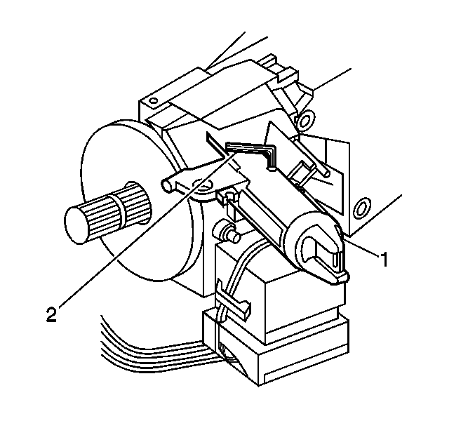
- Put the key in the steering column lock cylinder set (1).
- Turn the key to the START position.
- Install a 1/16 allen wrench (2) into the hole on top of the lock module assembly to release the steering column lock cylinder set retaining pin.
- Turn the steering column lock cylinder set (1) into the RUN position.
- Pull the steering column lock cylinder set (1) out from the lock module assembly.
- Remove the key from the steering column lock cylinder set (1).

Installation Procedure
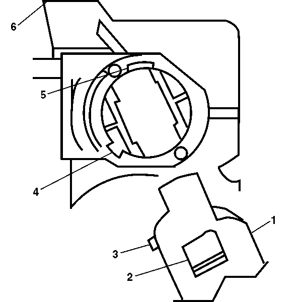
- Insert the key into the steering column lock cylinder set (1).
- Line up the locking tab (2) and the positioning tab (3) of the steering column lock cylinder set with the locking tab slot (5) and the positioning tab slot (4) in the lock module assembly (6).
- Push the steering column lock cylinder set (1) into the lock module assembly (6).
- Rotate the steering column lock cylinder set (1) in the lock module assembly (6) into all positions.
- Connect the ignition lock cylinder electrical connector to the wiring harness on the column.
- Install the upper and lower steering column trim covers. Refer to Steering Column Trim Covers Replacement - On Vehicle .
- Connect the negative battery cable to the battery. Refer to Battery Negative Cable Disconnection and Connection in Engine Electrical.

